

Technical articles
S-093N | 3BHB009885R0021 | Phase Module Usage Instructions | 3BHB009885R0021
Date: Mar 09, 2026 Views: 5927
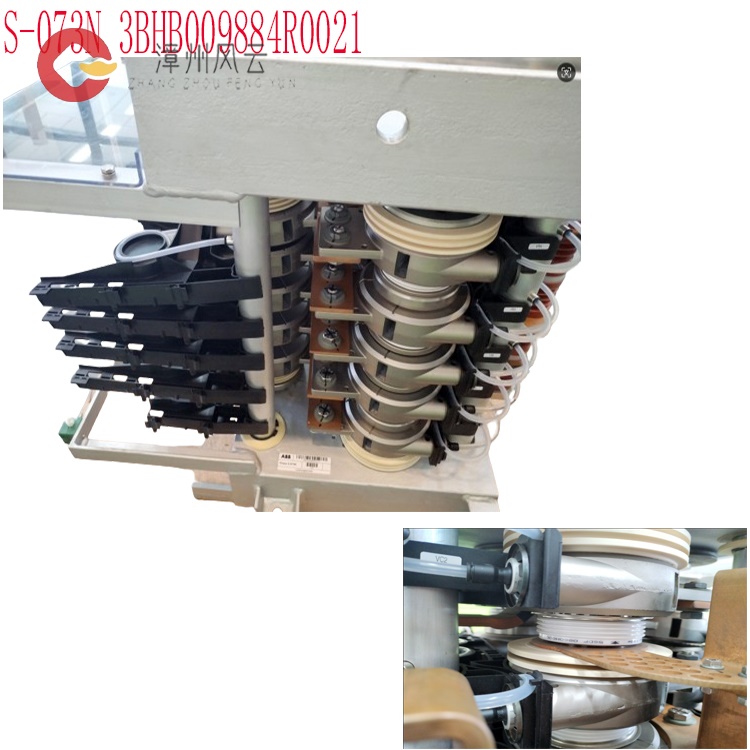
The S-093N 3BHB009885R0021 phase module is the core power control module of the ABB ACS6000/PCS6000 medium-voltage inverter/power supply system. Its usage requires consideration of system integration and module characteristics, and can be divided into the following dimensions:
Installation and Physical Deployment
Module Positioning: As a core component of the modular medium-voltage power conversion system, it needs to be integrated into the ACS6000 medium-voltage AC inverter or PCS6000 power supply system, working in conjunction with control units, drives, etc.
Mechanical Installation: Supports 19-inch standard rack mounting or DIN rail adaptation. The module dimensions are approximately 4×25.3×27.3cm, and it weighs 1.72-1.75kg. Its compact design facilitates rapid deployment. During installation, ensure the rack's center of gravity is stable to avoid tipping. Before disassembly, measure the DC bus capacitor voltage (must be below 60Vdc) and allow it to stand for 5 minutes before proceeding. After disassembly, wait 10 minutes before reinstalling.
Installation Requirements:
Compact modular design, supporting 19-inch rack mounting and hot-swappable functionality for easy and quick maintenance.
Dual-mode cooling system (air-cooled/water-cooled), ensuring an ambient temperature range of -25℃ to +70℃ and that the cooling system is free from blockages or leaks.
Input/output connections via rigid copper busbars, ensuring secure electrical connections that meet voltage (6kV/10kV) and current capacity requirements.
Installation Location: Wall-mounted units must support at least twice the load-bearing capacity, be 1.2-1.5m above the ground, and allow for ventilation around the perimeter (≥100mm top, ≥150mm bottom, ≥50mm sides). Cabinet-mounted units require good ventilation (airflow ≥1.2 times the heat dissipation requirement), should be at least 100mm away from heat-generating equipment, and preferably installed in the upper middle part of the cabinet. Electrical Connections
Main Circuit: Input connects to three-phase power (L1/L2/L3), equipped with a circuit breaker (1.2~1.5 times rated current) and a fuse; output connects to the motor (U/V/W), using copper core cables of matching wire diameter, covered with heat shrink tubing/crimped terminals, ensuring a secure and tight connection.
Control Circuit: Analog quantities (AI1/AI2) are grounded at one end using shielded wire, kept away from power lines; digital quantities (DI/DO) are distinguished as normally open/normally closed, terminals tightened securely; communication lines (e.g., RS485/Profibus) have consistent parameters (baud rate, address), with terminating resistors at both ends.
Grounding: PE terminal connected to ≥2.5mm² copper core wire, grounding resistance ≤4Ω, ensuring safety.
.jpg)
Hot-Swapping and Redundancy: Supports hot-swapping functionality; seamless switching to a backup module is possible in case of main module failure, reducing downtime. The module has built-in self-diagnostic function, displaying real-time operating status via LED indicators (RUN/ERR), with a solid red light indicating hardware failure. Environmental Adaptability: Employs a dual-mode cooling system (air-cooled/water-cooled), adaptable to extreme temperatures ranging from -25℃ to +70℃ and harsh industrial environments such as humidity and vibration. Protection rating: IP20.
Operation Procedure and Commissioning
Initial Power-On and No-Load Commissioning
No-Load Test: After closing the circuit breaker, the panel displays "READY" with no alarms. Measure the bus voltage (380V input ≈ 513V); perform a 5Hz trial run. If reversing, swap any two phases U/V/W; increase the frequency to 50Hz and monitor current (≤ rated), noise, and vibration. If abnormal, check the wiring or parameters.
Closed-Loop Commissioning: For scenarios such as constant pressure water supply, PID parameters need to be set, and the frequency is automatically adjusted through feedback signals.
Load Commissioning
Load Connection: Perform a 50% frequency trial run, adjusting acceleration and deceleration times (extend acceleration for difficult starts, extend deceleration for swaying stops); during full-load operation, monitor temperature (≤85℃) and current to ensure no overload or overheating.
System Configuration and Parameter Settings
Software Tools: Requires ABB Control Builder or Automation Builder engineering software for parameter configuration, fault diagnosis, and status monitoring. Supports industrial protocols such as PROFIBUS DP, Modbus TCP/IP, and OPC UA, and is compatible with ABB 800xA and AC 800M control systems and third-party PLCs (such as Siemens and Omron).
Core Parameters: Based on IGCT technology, employs a three-level NPC circuit, supports high-frequency switching (kHz level), efficiency ≥92%, harmonic distortion (THD) <3% (compliant with IEEE 519 standard). Configurable voltage/current phase synchronization accuracy enables four-quadrant operation (bidirectional power flow) and regenerative braking.
Dynamic Control: Integrates Direct Torque Control (DTC) technology to achieve real-time precise control of motor torque and speed; in STATCOM applications, it supports dynamic voltage control, fault ride-through, and reactive power compensation.
Operating Procedures and Safety Specifications
System Integration: As a core component of the modular medium-voltage power conversion system, it needs to work in conjunction with other modules (such as control units and drives). During operation, the inverter must be manually shut down via the control panel by entering "Menu→Turn To Bypass→YES" to put the system into bypass mode. During maintenance, ensure the UPS is in maintenance bypass or off state to avoid hot-plugging of static switch modules.
Safety Procedures: Before operation, ensure the DC bus voltage is below the safety threshold. When disassembling a module, first turn off the standby switch, wait 2 minutes, then remove the fixing screws. When pulling out the module, press the metal safety latch on the left side. After reinstallation, wait 10 minutes before restarting to ensure stable system operation.
Daily Operation:
Start/stop, speed/torque adjustment, and four-quadrant operation (supporting regenerative braking) are achieved through the system control unit.
LED indicator lights visually display the operating status (e.g., RUN/ERR). Status changes should be checked and recorded regularly.
Maintenance Guidelines:
The module supports hot-swapping. Before replacing a faulty module, power must be disconnected and the system must be in a safe state. Avoid operating while the system is powered on.
Regularly check the cooling system, connector tightness, and electrical insulation performance. Perform a comprehensive inspection quarterly.
The cooling system requires regular cleaning (air-cooled filter/water-cooled piping) to ensure heat dissipation efficiency.
.jpg)
Built-in Protection: The module integrates multiple protections including overvoltage/undervoltage, overcurrent, short circuit, and overtemperature. An isolation mechanism and alarm are automatically triggered when a fault occurs.
Diagnostic Process:
Locate the fault using the Control Builder tool based on LED indicators or system alarm codes.
Common faults, such as clamping diode malfunction (replace with 3BHB006457R0001 model) and cooling system failures, require troubleshooting step-by-step according to the official manual.
For major faults, contact the ABB global service network for software updates, spare parts supply, and on-site repair support.
Component Replacement: Clamping diodes must be of the same type (e.g., 3BHB006457R0001); water quick connectors must be replaced with the corresponding ID (e.g., 3BHB009885R5311) when upgrading; when replacing the battery module, all input connectors must be disconnected to avoid short circuit risks.
This module, with its high reliability, high efficiency, and modular
design, is widely used in motor drives, new energy power generation, rail
transportation, and power systems, and is a core component of ABB's
medium-voltage frequency converters and power systems. Strict adherence to
safety regulations and operating procedures is required during use to ensure
stable system operation and personnel safety.
Recommended related products:
3BHE023784R2630 PPD113B01
HIEE300788R0001 UAC095AE01
3BSE050199R1 PM866K02
3BSE018164R1 PM864AK02
3BHE025541R0101 PCD231B101
3BHB005243R0106 ABB
3BHE023784R2630 PPD113 B01-26-111001
3BHE017628R0002 PPD115A02
3BHE014135R2011 UAD149
3BHE014135R0011 UAD149A0011
3BHE014135R2511 UAD149A02-5-11
3BSE053242R1 PM891K02
3BSE053241R1 PM891K01
3BSE018100R1 PM860
3BSE018160R1 PM865K02
EXC3BSE018104R1 PM856K01
3BSE018168R1 PM851K01
3BSE018150R1 PM864K01
3BSE018160R1 PM861K02
3BSE018153R1 PM864K02
3BHB030478R0009 S-093H
3BHB009884R0004 S-073H
3BHB009884R0052 S-073H
3BHB009885R0002 S-093H
3BHB009885R0014 S-093M
3BHB009885R0104 S-093H
3BHB030478R0309 S-093H
3BHB009885R5311 S-093N
3BHB009885R0001 S-093N
3BHB009885R0021 S-093N
3BHB006457R0001 S-093N
3BHB030477R0207 S-073H
3BHB009885R0031 S-093S
3BHB009885R0004 S-093H
3BHB009884R0204 S-073H
3BHB009884R0013 S-073M
3BHB009885R0052 S-097H
3BHB009885R0005 S-093H
3BHB009884R0021 S-073N
3BHB009885R0052 S-097H
3BHB012897R0003 S-053M
S-073N 3BHB009884R0021
3BHB030478R0309 S-093H
3BHB009884R0021 S-073N
3BHB009885R5311 S-093R
3BHB009885R0063 S-093M
3BHB009885R0013 S-093M
More......
RELATED ARTICLE
Address
Room 205, Office Building, No.1 Chaoyang North Road, Longwen District, Zhangzhou City, Fujian Province
fengyunfadacai@qq.com
Sales consultant
Miss.Green
+86 15860249102