

Technical articles
How to debug the excitation controller 3BHE046836R0101 GFD563A101?
Date: Nov 15, 2025 Views: 5550
Preparations Before Commissioning
Hardware Check: Confirm that the module installation meets IP20 protection standards, with a heat dissipation space ≥5cm, secure wiring terminals, and grounding resistance ≤4Ω. Disconnect the excitation system from the busbar of the excitation transformer/generator, and use anti-static tools for operation.
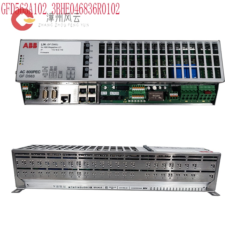
Integrity Verification: Verify that the controller model and serial number match the order. Check that accessories (such as wiring terminals and communication modules) are complete and free from physical damage.
Environmental Compatibility: Ensure the installation environment meets the requirements for temperature (-25℃~70℃), humidity (≤95% non-condensing), and electromagnetic interference (compliant with IEC 61000-4 standard). Leave ≥200mm of heat dissipation space around the installation.
.jpg)
Tool Preparation: Equip with an EXOM-Ⅱ type open-loop tester (or equivalent equipment), dynamic signal recorder, power analyzer, oscilloscope, and insulation resistance tester.
Software Configuration: Load the control program using ABB dedicated software (such as UNITROL Configurator, Control Builder M), and configure the communication protocol (such as PROFIBUS DP-V1), node address (5-bit identifier), and data type (such as protection settings, operating status).
Wiring Specifications: Connect the power supply (such as 380V AC), signal (such as CT/PT), and control lines according to the wiring diagram. Ensure the grounding resistance is ≤4Ω. Separate signal lines from power lines (spacing ≥200mm) to avoid short circuits or loose connections.
Software and Parameter Configuration
Communication Settings: Configure Ethernet/serial communication parameters (such as baud rate 9600, address 1-32), supporting protocols such as PROFIBUS DP and Modbus, ensuring compatibility with the host computer (such as the 800PEC controller) or the power plant SCADA system.
Control Algorithm Configuration: Set PID parameters, limiter thresholds (e.g., V/Hz limit to 110% of rated value, excitation current limit to 200% of maximum value), soft-start excitation time (≤20s), etc., using ABB dedicated tools (such as UNITROL Configurator).
.jpg)
Protection Function Activation: Configure overcurrent, overvoltage, undervoltage, rotor grounding, and other protection parameters, and set alarm and trip delays (e.g., forced excitation limit delay of 10s).
Open-Loop Test and Parameter Calibration
Small Current Test:
Connect the three-phase output of the open-loop tester to the AC side of the rectifier cabinet, and connect a load resistor (100-200Ω) to the DC side.
Set the excitation regulator settings (e.g., P312 = local ECT control, P412 = plant power mode, P504 = excitation transformer low-voltage side rated value), and verify that the phase sequence is positive.
Perform the excitation start-up operation (press "RELEASE+EXC ON"), gradually adjust the control angle (e.g., from -1000° to 1000°), and observe the rectified output waveform (containing 6 regular wavefronts within 0-20ms) to ensure normal thyristor triggering.
Core Debugging Steps
Single-Unit Function Test
Power Supply Test: Use a multimeter to verify that the power supply voltage (e.g., DC 24V) meets the controller requirements. Observe the power indicator light status to ensure there are no abnormal alarms.
Excitation Regulation Test: Manually adjust the excitation current reference value and verify the controller output response (e.g., step response time ≤ 50ms). Check whether the excitation voltage/current waveform meets the design requirements.
Limiter Verification:
V/Hz Limiter: Simulate frequency decrease (e.g., 50Hz → 45Hz) to verify whether the controller automatically reduces the excitation voltage to prevent over-magnetic flux.
Excitation Current Limiter: Verify the inverse-time characteristic through a step test (e.g., triggering the limit after 10 seconds of strong excitation peak value of 200%) to ensure effective rotor thermal overload protection.
Soft Excitation Function: Verify whether the generator terminal voltage smoothly rises to 95% of the rated value (≤20s) during the residual voltage excitation stage to avoid overshoot.
System Integration and Dynamic Testing
Grid Connection Synchronization Test: Before generator grid connection, verify the phase synchronization capability between the controller and the grid voltage (e.g., phase difference ≤5°) to ensure that grid current harmonics (THD ≤5%) meet the standard.
Dynamic Response Test: Simulate sudden load changes (e.g., sudden increase/decrease of 50% load) to verify the controller's dynamic response (e.g., excitation current adjustment time ≤200ms) to ensure system stability.
Protection Function Test: Simulate fault scenarios (e.g., CT disconnection, rotor grounding) to verify the correctness of protection action logic (e.g., tripping, channel switching) and the completeness of fault records.
Communication and Remote Monitoring
Communication Testing: Verify the accuracy of controller response and data feedback (e.g., operating status, fault records) by sending commands (e.g., setpoint modification, start/stop control) via a host computer.
Remote Diagnostics: Utilize the ABB Ability™ platform for remote parameter monitoring and fault diagnosis, supporting firmware upgrades and configuration backups.
Parameter Calibration:
Adjust PID parameters (e.g., proportional gain, integral time) to optimize step response (overshoot ≤30%, settling time ≤5 seconds).
Calibrate protection thresholds (overcurrent, overvoltage, underexcitation) to ensure matching with generator parameters.
Dynamic Performance Testing
Step Response Test:Apply a ±10% voltage step under no-load rated voltage, record the generator terminal voltage and excitation current waveforms, and verify that overshoot, settling time, and oscillation counts meet national standards (e.g., overshoot ≤50%, settling time ≤10 seconds).
Voltage/Frequency Characteristic Test Simulate generator speed changes (e.g., ±5% of rated frequency) to test the excitation controller's ability to maintain voltage stability. PSS Function Verification: Evaluate the positive damping effect provided by the Power System Stabilizer (PSS) through frequency disturbance tests, ensuring system oscillations subside within 10-15 seconds.
Protection Functions and System Integration
Protection Function Testing: Verify the correct operation of overexcitation, underexcitation, volt-hertz limiting, rotor grounding protection, etc., ensuring that the rotor overvoltage multiple during demagnetization is ≤4-6 times the rated value.
Communication and Integration: Test the communication stability with the host computer (e.g., AC800PEC system), confirming that data frame transmission (e.g., setting values, status, fault records) is without loss or errors.
Temperature Rise and Insulation Testing: Monitor the module temperature rise under full load operation, ensuring it does not exceed the design limit; periodically measure insulation resistance (≥1MΩ/kV).
Maintenance and Records
Regular Maintenance: Tighten internal cable connections, clean the module surface, measure insulation resistance, and update software every six months.
Data Logging: Record waveforms, parameter settings, and test results during the debugging process to create a complete document for subsequent analysis and troubleshooting.
Precautions:
Power must be disconnected during the entire debugging process. Avoid hot-plugging modules. High-risk steps (such as excitation and step tests) require double-checking.
Strictly adhere to ABB technical specifications and industry standards (such as IEC 60204 and IEC 61000-2-4) to ensure parameter settings are consistent with the system design.
Troubleshooting: If an abnormal alarm is encountered (such as F03 overcurrent fault), prioritize checking parameter settings, wiring, and sensor status. If necessary, use ABB diagnostic tools to analyze the fault log.
If an anomaly is encountered, prioritize reading the error code through the fault diagnosis interface (such as RS485/CAN bus) and analyze the cause in conjunction with the log.
Dedicated Tools: Use software such as ABB Drive Composer and UNITROL
Configurator for parameter configuration and monitoring, and use a multimeter
and oscilloscope for electrical parameter measurement.
Related product recommendations:
PPD113B03-26-100110 3BHE023584R2634
PPD115A102 3BHE017628R0102
3BHE030410R3011 PPD117A3011
3BHE020455R0103 PPD103B103
3BHE040375R103E PPD512A10
3BHE040375R1023 PPD512A10
3BHE039724R0C3D PPD513AOC
8R37-2021-21-3101 PCD2000
3BHE022291R0101 PCD230A
3BHE057901R0101 PCD235C101
3BHE028915R0101 PCD237A101
3BHE046836R0102 GFD563A102
3BHE046836R0101 GFD563A101
3BHE041343R0102 PCD530A102
PPD113-B03-23-111615 3BHE023584R2365
PPD113B01 3BHE023784R1023
3BHE017628R0102 PPD115
More......
RELATED ARTICLE
Address
Room 205, Office Building, No.1 Chaoyang North Road, Longwen District, Zhangzhou City, Fujian Province
fengyunfadacai@qq.com
Sales consultant
Miss.Green
+86 15860249102