
How to troubleshoot 3BHE046836R0101 GFD563A101 ABB?
Date: Oct 11, 2025 Views: 8908
Basic Hardware Check
Power Supply and Connection Verification
Check whether the 24V DC power supply is normal (a solid RUN light indicates normal operation; a flashing or off light requires troubleshooting the power module).
Confirm that signal cables (such as DI/DO and communication interfaces) are securely connected and not loose or oxidized. Check that the cable shield is grounded (ground resistance ≤ 4Ω).
Verify module status indicators:
If the ERROR light is on, this indicates a possible hardware failure (such as module damage, counter error) or software error (operating system failure, watchdog timeout). Further analysis is required based on the error code.
If the FAULT light is on, this indicates a logic error (such as a program exception), configuration corruption, or I/O error. Check the program logic and configuration files.
If the OSL light is flashing, this indicates an emergency operating system load failure and requires firmware re-flashing.
.jpg)
Software and Parameter Configuration
Parameter Settings:
Use official ABB software (such as DriveWindow or DriveComposer) to check parameter settings, including PID parameters, input/output mapping, safety functions (such as STO and emergency stop), and communication protocols (Modbus, Profibus, etc.).
Ensure that the parameters match the load characteristics, motor parameters (such as rated current and speed), and process requirements.
Firmware and Software Updates:
Confirm that the controller firmware version is up to date and upgrade if necessary to fix known vulnerabilities or optimize performance.
Check that the software configuration is compatible with the hardware version to avoid functional abnormalities caused by version mismatches.
Communication and Network Troubleshooting
Bus Communication:
If using a bus such as PROFIBUS or CAN, check that the bus connection, terminal resistors, baud rate, and node address are correctly configured.
Verify that the GSD file matches the slave device to eliminate communication failures or data errors caused by configuration errors.
Host Computer Communication:
Check the communication protocol, data frame format, and handshake signals between the host computer and the controller to ensure they are functioning properly. Eliminate communication interruptions caused by software conflicts or network delays.
Physical Environment Check
Clean dust from the device and ensure the cooling airflow is unobstructed. Check the fan operating status (such as speed and noise) to prevent overheating.
Verify environmental adaptability: Avoid extreme temperatures (-40°C to 70°C), high humidity (>90% RH), or strong electromagnetic interference. Install filters or shielding devices if necessary.
Communication and Protocol Configuration Troubleshooting
Network Parameter Verification
PROFIBUS DP: Check that the node address is unique and does not exceed 31, that the baud rate and data format (e.g., 8-bit data, 1 stop bit) are consistent with those of the master, and that the GSD file is loaded correctly.
Ethernet: Configure the IP address and subnet mask, enable TCP/IP communication, and ensure compatibility with the host computer/PLC protocol (e.g., EtherNet/IP, Modbus).
Data consistency mode: When processing DP input data, lock the VME_MAS_RXPG_LOCK bit to prevent the host and embedded processor from accessing the data page simultaneously.
Communication Troubleshooting
If a "data block length exceeds the requested length" error (e.g., 0x0A00, 0x0B00) occurs, check the slave address, data block size, and remote station status.
Use a network analyzer or diagnostic tool (e.g., ABB Fault Code Manual) to analyze the communication frame and troubleshoot signal attenuation, delay, or configuration conflicts.
3. Software and Parameter Configuration
Basic Parameter Settings
Use ABB-specific tools (e.g., DriveWindow, Control Builder) to configure protection settings (e.g., overload current, short-circuit current thresholds), control mode (voltage/reactive power regulation), and communication parameters.
Check the firmware version (e.g., V217) to ensure compatibility with the hardware. Firmware updates must be written to the non-volatile ROM to avoid interruptions and system damage.
Advanced Function Configuration
Enable fault diagnostics (e.g., F05 undervoltage, F19 input phase loss), set alarm thresholds and response strategies (e.g., STO function, emergency stop categories 0/1/2).
Configure safety functions (e.g., Safe Torque Off STO) to ensure compliance with safety standards such as IEC 60204 and ISO 13850.
Fault Code Analysis and Troubleshooting
Common Error Codes
Overcurrent Fault (F0001)
Causes: Excessive load (e.g., mechanical jam, overtightened drive belt), motor/cable short circuit, short acceleration time, or damaged IGBT module.
Solution:
Check the motor load and mechanical transmission components to eliminate any jamming or overload;
Measure the motor/cable insulation resistance (normally >5MΩ) and check for short circuits;
Extend the acceleration time (parameter 2202) to avoid current surges;
Check the IGBT module (use a multimeter's diode range to measure the forward resistance between the C-E terminals to be approximately 0.34MΩ, and the reverse resistance to be infinite); replace if abnormal.
Overvoltage Fault (F0002)
Cause: Power supply voltage too high, deceleration time too short, brake resistor failure, or aging of the DC bus capacitor.
Solution:
Confirm that the input voltage exceeds the inverter's rated value (e.g., a 400V inverter bus voltage >840V triggers an alarm);
Extend the deceleration time (parameter 2203) to avoid excessive energy regeneration;
Check the brake resistor value and brake unit status, and replace if necessary;
Check the DC bus capacitor capacity (a 20% decrease in capacity requires replacement).
Overheating Fault (F0003)
Cause: Cooling fan failure, dust accumulation on the radiator, excessively high ambient temperature, or continuous overload.
Solution:
Clean dust from the radiator and fan, and ensure unobstructed airflow.
Check that the fan is operating properly (if low speed or unusual noises occur, replace the fan).
Lower the ambient temperature or increase ventilation.
Reduce the load to the rated range to avoid prolonged overload operation.
Undervoltage Fault (F0006)
Cause: Power phase loss, rectifier bridge failure, aging DC bus capacitor, or blown fuse.
.jpg)
Solution:
Check that the three-phase power supply is balanced and eliminate phase loss.
Test the rectifier bridge (forward resistance approximately 0.37MΩ, reverse resistance infinite). Replace any abnormalities.
Replace aging capacitors and check fuse status.
Communication Fault
Cause: Poor fiber connection, baud rate mismatch, grounding interference, or module failure.
Solution:
Check the fiber optic connector for cleanliness and secure connections (for example, the master-slave bus fiber needs to be treated with a precision cleaning agent);
Confirm the Profibus terminal resistor matching and baud rate setting (if consistent with the master);
Check for ground interference and ensure that signal and power cables are routed separately (with a spacing > 200mm);
Use LED indicators (such as RUN/ERR) to determine module status. A solid red light indicates a hardware fault.
F05 (Undervoltage): Check the DC bus voltage and troubleshoot aging of the power module or capacitors or improper undervoltage protection threshold settings.
F19 (Input Phase Loss): Verify the three-phase power connections and check the phase detection circuit and motor current limit settings.
n05 (Input Phase Loss Warning): The advanced control system may choose to end the current cycle or initiate a drive stop. Check the program logic and control strategy.
MAINS BTB, F16: Main power disconnect warning. Check the power contactor and emergency stop button.
Extended Fault Information
If the status word returns "Invalid Other," check the acyclic message header, data type identifier (ID0-ID4), and frame count to avoid data conflicts or out-of-range conditions (e.g., >240 bytes).
Model-Specific Notes
3BHE046836R0101 (Servo Amplifier):
Pay attention to braking power exceeding the limit (e.g., "n02 Braking Power Exceeded" warning). Check the braking circuit and load matching.
An F19 error is triggered when an input phase is lost. Check the power phase and grounding.
The holding brake function requires coordination with the electromechanical "closed" contact to ensure safe braking.
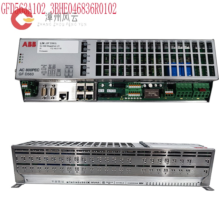
GFD563A101 (Field Controller):
As a PLC expansion module, parameters must be configured using ABB Control Builder or Automation Builder.
Check the Profibus terminal resistor and baud rate to troubleshoot signal interference.
Module status is determined by the LED indicator (e.g., a solid red light indicates a hardware fault).
Maintenance and Optimization
Regular Maintenance
Tighten internal cables and measure insulation resistance every six months; clean equipment dust; and inspect grounding and shielding systems.
Verify the redundant power supply switching function and ensure the undervoltage protection threshold is set appropriately to avoid false alarms.
General Troubleshooting Steps
Safety Preparation: Shut down the machine and disconnect the power supply, allowing the capacitors to discharge (approximately 5 minutes) to avoid the risk of electric shock.
External Inspection: Confirm that the power and control cables are securely connected and not loose or damaged.
Fault Code Analysis: Check the fault code (e.g., F0001, F0002) on the operation panel and refer to the manual to determine the cause.
Hardware Inspection: Use a multimeter to check the power supply voltage and resistance, and inspect components such as capacitors, fans, and IGBTs.
Software Reset: Attempt to clear the fault using the reset button on the panel or parameter settings (e.g., 1604 FAULT RESET SEL).
Professional Support: If the problem persists, contact ABB technical support or a professional maintenance technician to avoid secondary damage caused by blind operation.
Environment and Maintenance
Environmental Factors:
Ensure the equipment's operating environment meets requirements (e.g., temperature -10°C to 50°C, humidity ≤ 90% non-condensing) to prevent malfunctions caused by high temperature, high humidity, dust, or vibration.
Check that the cooling system (e.g., fans and heat sinks) is clean and that airflow is unobstructed.
Regular Maintenance:
Perform regular equipment cleaning, connection tightening, parameter calibration, and functional testing to extend equipment life and prevent potential malfunctions.
Safety Function Verification:
Emergency Stop and Safe Torque Off (STO):
Test the emergency stop button, safety door switch, and STO function to ensure they quickly cut power and lock the equipment in the event of a fault or hazard.
Safety Circuit:
Check that the safety circuit complies with standards such as IEC 60204 and ISO 13849. Ensure proper grounding, shielding, and wiring to prevent malfunctions caused by electromagnetic interference.
Performance Optimization
Control cycles and communication rates are adjusted based on application scenarios to optimize response time. Combined with ABB intelligent sensor technology, energy efficiency is improved through real-time monitoring and data analysis.
Related product recommendations:
3BHB009885R0013 S-093M
3BHB009885R0052 S-097H
3BHB009885R0063 S-093M
3BHB009885R0005 S-093H
3BHB009885R5311 S-093R
35SHY3545L0014 S-073N
3BHB009884R0021 S-073N
3BHB009885R0052 S-097H
3BHB030478R0309 S-093H
3BHB012897R0003 S-053M
S-073N 3BHB009884R0021
3BHE041430R0001 ABB
3BHE041429R0001 ABB
3BHE041418R0001 ABB
3BHE041414R0001 ABB
3BHS393721 E01 ABB
3BHS600000 E40 ABB
3BHS606571 E49 ABB
3BHS537463 E72 ABB
3BHS600000 E87 ABB
More......
RELATED NEWS
Address
Room 205, Office Building, No.1 Chaoyang North Road, Longwen District, Zhangzhou City, Fujian Province
fengyunfadacai@qq.com
Sales consultant
Miss.Green
+86 15860249102

.jpg)