

How to set up ABB 3BHE046836R0101 GFD563A101?
Date: Oct 11, 2025 Views: 1185
Device Overview
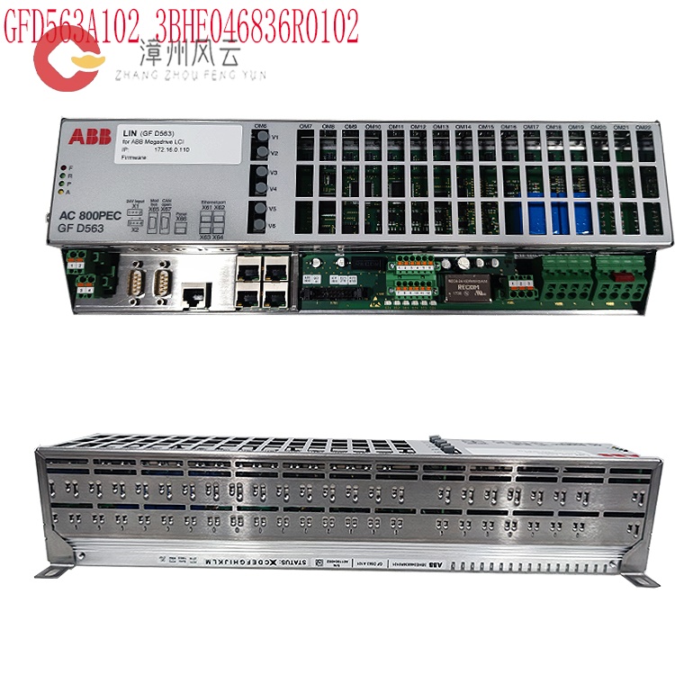
Model and Application: The GFD563A101 is an ABB excitation controller or frame circuit breaker used in low-voltage power distribution systems to protect circuits from overloads, short circuits, and other faults. It is widely used in industries such as gas, water supply, metallurgy, power generation, and papermaking.
.jpg)
Technical Features: Supports fast control cycles (e.g., the 100-microsecond response of the AC800PEC system), reactive power regulation, voltage stability control, and fault diagnostics.
Communication Interface: Supports industrial protocols such as PROFIBUS and Ethernet. Network parameters (e.g., node address and baud rate) must be configured and a GSD file imported.
3BHE046836R0101: Setting up the GFD563A101 requires the following systematic steps, covering four core modules: hardware connection, software configuration, communication protocol adaptation, and safety protection:
Hardware Installation and Physical Connections
Power Supply and Grounding
Ensure a stable power supply (e.g., the DC bus voltage meets module requirements). Regular switching and testing of the redundant power supply is recommended (quarterly).
The grounding system utilizes a grid-type shield (resistance ≤ 4Ω) and is equipped with an SPD surge protector to protect against electromagnetic interference and lightning strikes.
Signal and power cables should be routed separately, with spacing ≥ 200mm. High-voltage equipment (such as inverters) should not be placed in the same cabinet.
I/O Module Expansion
The basic configuration supports 62 mixed I/Os (30 digital inputs including 2 shaft encoders, 2 analog inputs, 28 digital outputs, and 2 high-speed outputs). This can be expanded to 1024 I/Os using local/remote expansion modules (up to 1000 meters).
.jpg)
Remote expansion requires compliance with signal attenuation standards (such as PROFIBUS DP length limits) and the use of shielded cable and the installation of filters (such as LC filters).
Software Configuration and Parameter Settings
Communication Protocol Adaptation
PROFIBUS DP Configuration: Loading a GSD file is required to ensure compatibility between the master and slave devices. In the PROFIBUS master configuration window, the node address must match the address selected in the "Set Slave" dialog box. If no matching GSD file is found, the identifier byte will appear red and you will need to scan the network identifier byte in ProSoft Configuration Builder and manually configure it.
EtherNet/IP Configuration: The IP address, gateway, and DNS settings must be configured in PanelBuilder 32 software to support remote monitoring and data acquisition.
DF1 Port Settings: The default baud rate is 9600, with 8 data bits, 1 stop bit, and parity options of none, even, or odd; when communicating with an SLC controller, the parity setting must be fixed to none.
Network Configuration:
PROFIBUS Settings: Assign the node address through the master (e.g., PLC). Configure the network scan window and ensure that the GSD file matches the slave device module.
Ethernet Settings: Configure the IP address and subnet mask, enable TCP/IP communication, and support high-speed data transmission (e.g., ABB's AC800PEC system). I/O Module Configuration: Configure digital/analog input/output modules according to application requirements to ensure signal compatibility with the host computer or PLC.
Register and Data Management
DP input data is accessed through PROFI_USR registers (e.g., vmeMasRxPage). The VME_MAS_RXPG_LOCK bit in the pfbMasCoherFlags register must be asserted to prevent the embedded processor and the host from accessing the same page simultaneously.
In data consistency mode, the card's embedded processor sets the page reference at the end of each scan, ensuring data validity during host read operations.
3. Safety Protection and Fault Diagnosis
Protection Mechanism Configuration
Multiple protection functions, such as overcurrent, overvoltage, and overtemperature, are integrated, enabling predictive maintenance (e.g., input phase loss and undervoltage alarms) through ABB smart sensor technology.
Redundant power supplies and lightning protection modules are configured to ensure continuous system operation. Strict maintenance regulations must be followed in hazardous areas (e.g., explosion-proof environments) to avoid loss of explosion-proof certification.
Troubleshooting Process
Status Indicator Interpretation: A solid fill indicates normal operation; a flashing fill indicates communication failure or a hardware fault; an unfilled fill indicates a hardware fault.
Error Handling: Use a network analyzer or multimeter to detect voltage/current anomalies. If a bus-off interrupt occurs, select the "Hold Reset" or "Reset and Continue Communication" strategy according to the IEC 60204 standard.
Software Parameter Configuration
Basic Parameter Settings:
Protection Settings: Set overload current and short-circuit current thresholds, delay times, and undervoltage/overvoltage protection parameters.
Control Mode: Select voltage regulation, reactive power control, or stability enhancement mode (e.g., dynamic stability control).
Communication Parameters: Baud rate (e.g., 9600/19200), data bits, stop bits, and parity check. Ensure consistency with the master station's communication protocol.
Advanced Function Configuration:
Fault Diagnosis: Enable fault logging and alarm output (e.g., F05 undervoltage fault, F19 input phase loss).
Safety Functions: Configure STO (Safe Torque Off), Emergency Stop (Category 0/1 Stop), and locking mechanisms.
Firmware and Software: Use ABB-specific tools (such as DriveWindow and Control Builder) for parameter programming and firmware updates.
System Integration and Commissioning
Network Scanning and Configuration: Import the GSD file into the PROFIBUS master, assign slave device addresses, and verify communication status (such as "Connected").
Parameter Verification: Send test commands (such as setpoint transfer and status query) from the host computer to confirm that the device responds correctly.
Error Handling:
Communication Failures: Check the lock bit (such as VME_MAS_RXPG_LOCK) to ensure data access synchronization between the host and embedded processor.
Parameter Errors: Verify data type identifiers (ID0-ID4) and frame counts to avoid data conflicts.
Hardware Failures: Check cable connections and module status indicators (a flashing fault indicator indicates a hardware problem).
System Integration and Expansion
Modular Expansion
Compatible with ABB's AC 800M series master control modules (such as the PM851 and PM861), supporting system integration; parameter configuration and debugging are performed using Automation Builder engineering software.
Seamless integration with third-party devices (such as PLCs and SCADA systems) is supported, requiring verification of protocol compatibility (such as Modbus and CANopen).
Maintenance and Optimization
Regular Inspection: Tighten internal cables, measure insulation resistance, and clean equipment dust every six months.
Performance Optimization: Adjust control cycles and communication rates based on application scenarios to optimize response time.
Troubleshooting: Use diagnostic tools (such as ABB's fault code manual) to analyze error logs and update firmware or software patches.
Precautions
Safety Compliance: Complies with safety standards such as IEC 60204 and ISO 13850 to ensure operator safety.
Compatibility Verification: Confirm device compatibility with existing systems (such as PLCs and inverters) to avoid configuration conflicts.
Energy Management Optimization
As an excitation logic controller, it supports automatic/manual adjustment of excitation current/voltage to maintain grid stability. It also integrates overvoltage/overcurrent protection and supports remote monitoring and configuration, making it suitable for thermal, hydropower, and renewable energy power plants.
Integrated with ABB's intelligent sensor technology, it optimizes equipment efficiency and reduces energy consumption through real-time monitoring and data analysis.
Summary: The 3BHE046836R0101 GFD563A101 configuration requires
comprehensive consideration of hardware connectivity, software configuration,
security protection, and system integration. It is recommended to consult ABB's
official technical documentation (such as product manuals and compatibility
lists) and verify the validity of your configuration through simulation testing.
For complex systems, it is recommended to contact ABB technical support or a
professional maintenance team for in-depth diagnosis and optimization.
Related product recommendations:
3BHE046836R0102 GFD563A102
3BHE046836R0101 GFD563A101
UCD846A101
UDD847A101
PPD117A3011
3BHE020455R0103
3BHE040375R1023
PPD103B103
PPD512A10-150000
PPD512A10
3BHE040375R103E
3BHE039724R0C3D
3BHE041576R3011
GFD563A102 3BHE046836R0102
GF D563 3BHE046836R0101
PPE091A101
3BUR001401R1
PU512V2
PU515A
PU515A 3BSE032401R1
More...
RELATED NEWS
Address
Room 205, Office Building, No.1 Chaoyang North Road, Longwen District, Zhangzhou City, Fujian Province
fengyunfadacai@qq.com
Sales consultant
Miss.Green
+86 15860249102