
How to solve the problem of ABB 3BHE046836R0101 not being able to connect to the computer?
Date: Oct 11, 2025 Views: 1231
If the ABB 3BHE046836R0101 device fails to connect to a computer, you need to troubleshoot the hardware connection, communication parameters, software configuration, and network environment from multiple perspectives. The specific steps are as follows:
Hardware Connection Check
Physical Interface Verification
Confirm that the cable type (e.g., Ethernet, PROFIBUS DP, RS-232/485) matches the device interface and check for loose, oxidized, or damaged connectors. For example, for PROFIBUS DP networks, ensure the cable length is ≤ 100 meters (at high speeds) and that the terminal resistors are configured correctly.
Check the power connection: Ensure the control module has a stable power supply (e.g., an AC/DC power adapter) and that the power module indicator is functioning properly (a solid fill indicates normal operation; a flashing indicator may indicate undervoltage or a hardware failure).

Verify that peripherals such as I/O modules, sensors, and actuators are properly wired to avoid signal interference (e.g., separate power and signal cables, with a spacing of ≥ 200mm).
Hardware Status Diagnosis
Observe the status indicators:
Communication Status: A solid fill indicates normal operation; a flashing fill indicates communication is not established. An unfilled fill may indicate a hardware failure.
Fault Status: A flashing fill may indicate the application is not loaded or a configuration error (such as a node address conflict). A solid fill indicates troubleshooting a hardware failure.
Use a multimeter to check for normal voltage and current. Check components such as capacitors and IGBTs for signs of burning or swelling.
Software and Driver Configuration
Driver Installation and Updates
Install official ABB drivers (such as DriveComposer and Control Builder) to ensure compatibility with the operating system (such as Windows 10/11 or Linux). If the driver version is outdated, upgrade to the latest version to fix known compatibility issues.
Use ABB's dedicated configuration tools (such as PanelBuilder 32 and Automation Builder) to program parameters to avoid configuration conflicts caused by using third-party tools.
Communication Parameter Matching
Network Parameters: The IP address, subnet mask, and gateway must be on the same subnet as the computer to ensure there are no conflicts. For example, for EtherNet/IP, you need to configure the gateway and DNS in PanelBuilder 32.
.jpg)
Protocol and Baud Rate: Check that the baud rate (e.g., 9600/19200), data bits, stop bits, and parity for protocols such as PROFIBUS DP, Modbus, and CANopen are consistent with those in the PC software. If using the DF1 port, ensure the baud rate matches (9600 by default).
Node Address: In a PROFIBUS DP network, node addresses must be unique and not exceed the maximum limit (e.g., 31) to avoid address conflicts.
Communication Link and Network Environment
Bus Communication Verification
If using PROFIBUS DP, assign node addresses through the master, configure the network scan window, and import the GSD file to ensure slave device compatibility. If no matching module is found in the GSD, manual configuration must be performed using ProSoft Configuration Builder.
Check that the bus connector and terminal resistor are correctly installed to prevent communication failures caused by signal reflection or attenuation.
Firewall and Security Software
Temporarily disable your computer's firewall or antivirus software (such as Windows Defender or McAfee) to rule out connection issues caused by port blocking.
Ensure that the network ports (such as TCP 502 and UDP 161) between the computer and the device are not occupied, and that no other programs are using the same resources.
Driver and Software Configuration
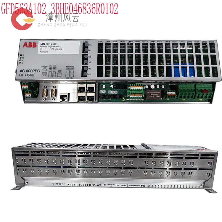
Driver Installation: Install ABB's official drivers (such as DriveWindow or Drive Composer) or compatible industrial communication drivers (such as Modbus or Profibus). For example, the GFD563A101 module must match the corresponding driver version to avoid connection failures due to driver incompatibility.
Protocol and Parameter Matching:
Network Configuration: If connected via Ethernet, ensure that the computer and device IP addresses are on the same network segment (such as 192.168.1.x), have the same subnet mask, and no IP conflicts. Devices typically support TCP/IP; the correct IP address, gateway, and port must be set in the configuration software.
Serial Port Parameters: If using a serial port, verify parameters such as the baud rate, parity, data bits, and stop bits. For example, the default baud rate for ABB robot serial ports is 9600, 8 data bits, 1 stop bit, and no parity. These settings must be consistent with those in the computer's serial port debugging tool (such as SecureCRT or Putty).
Software and System Settings
Firewall and Security Software: Temporarily disable your computer's firewall or security software (such as Windows Defender or third-party antivirus software) to prevent them from blocking communication ports or drivers.
Port Usage Check: Use a system command (such as netstat -ano in Windows) to check if the target port is occupied by another program. Restart the computer or release the port if necessary.
Software Compatibility: Ensure that the configuration software used (such as ABB Drive Composer) is compatible with the operating system version and is up to date to fix known bugs.
Device Configuration
Communication Protocol Activation: Enable the corresponding communication protocol (e.g., Modbus TCP, Profibus DP) in the device configuration interface (e.g., ABB AC800PEC controller) and set the slave address to match the one on the computer.
GSD File Import: If using a bus such as PROFIBUS, import the corresponding GSD file for the device into the configuration software (e.g., Step 7, TIA Portal) to ensure that the master can recognize the slave device.
.jpg)
Diagnostic Tool Usage: Use the device's built-in diagnostic features (e.g., LED status indicators, error code query) or ABB-provided diagnostic tools (e.g., System Manager) to check communication status and locate faults (e.g., bus disconnect, data frame errors).
Firmware and System Optimization
Firmware Update
Check the controller firmware version (e.g., V217) and upgrade to the latest version using ABB's official tools (e.g., Firmware Update Utility) to fix known communication vulnerabilities or performance issues.
Update the computer software (e.g., PLC programming software) to a compatible version to avoid communication anomalies caused by version mismatches.
System Compatibility Verification
Ensure that the computer operating system is compatible with the device drivers and software. For example, some ABB tools only support specific Windows versions; confirm the system requirements.
If using a virtual machine or remote desktop, configure network bridging mode to ensure direct access to the physical network interface.
Troubleshooting and Professional Tools
Error Code Interpretation
Locate the problem based on the status word or error code. For example, F02 (overvoltage) may be caused by a faulty brake resistor or power supply fluctuations; F19 (input phase loss) requires checking the power phase connection and grid stability.
Use professional tools (such as a multimeter or oscilloscope) to measure signal waveforms and analyze communication protocol data packets (such as the CAN bus frame structure) to accurately locate the fault.
Professional Support
If self-troubleshooting is unsuccessful, contact ABB official technical support or an authorized service provider and provide the device serial number, fault symptoms, and configuration logs for a customized solution.
Advanced Troubleshooting Steps
Firmware and Software Updates: Check that the device firmware and configuration software are up to date. Updates can fix known communication issues.
Replacement Testing: Eliminate the possibility of hardware failure by replacing the network cable, USB cable, or serial port card on the computer.
Preventive Maintenance
Regularly check the status of hardware, including connectors, cables, and power modules. Clean the device of dust and ensure the cooling system is functioning properly.
Back up configuration data and parameter settings, and record hardware and software version information to facilitate quick recovery or upgrades.
Summary: Connection problems are often caused by hardware connection anomalies, driver/protocol mismatches, incorrect software settings, or improper device configuration. Troubleshoot layer by layer, starting from the physical layer, then the data link layer, and finally the application layer. Use the device manual and specialized tools to locate the problem.
Related product recommendations:
3BHB009885R0013 S-093M
3BHB009885R0052 S-097H
3BHB009885R0063 S-093M
3BHB009885R0005 S-093H
3BHB009885R5311 S-093R
35SHY3545L0014 S-073N
3BHB009884R0021 S-073N
3BHB009885R0052 S-097H
3BHB030478R0309 S-093H
3BHB012897R0003 S-053M
S-073N 3BHB009884R0021
3BHE041430R0001 ABB
3BHE041429R0001 ABB
3BHE041418R0001 ABB
3BHE041414R0001 ABB
3BHS393721 E01 ABB
3BHS600000 E40 ABB
3BHS606571 E49 ABB
3BHS537463 E72 ABB
3BHS600000 E87 ABB
More......
RELATED NEWS
Address
Room 205, Office Building, No.1 Chaoyang North Road, Longwen District, Zhangzhou City, Fujian Province
fengyunfadacai@qq.com
Sales consultant
Miss.Green
+86 15860249102


.jpg)