
.jpg)
.jpg)
The processor unit features an integrated high-speed fiber-optic PowerLink interface (supporting up to 36 bidirectional fiber-optic connections) for linking the underlying power converter interface boards with high-speed I/O modules. Fiber-optic transmission not only eliminates signal interference in high-voltage, high-electromagnetic-field environments but also provides high-potential electrical isolation between the control unit and the power cabinets. Furthermore, the system employs a high-precision clock synchronization mechanism, ensuring that voltage and current signals acquired across multiple channels are strictly aligned along the time axis—thereby guaranteeing phase accuracy for closed-loop regulation.
Many products have not yet been listed online; please contact us for information on additional items.
If there is a discrepancy between a product model and its displayed image, the model number shall take precedence. Please contact us if you would like to see specific product photos; we can arrange for them to be taken at our warehouse for your confirmation.
We operate 76 shared warehouses globally, so it may occasionally take a few hours to provide you with an accurate response—we appreciate your patience. Rest assured, we will address your inquiries as quickly as possible.
3BHE039724R2565– Alternative Designations:
Programmable Logic Control Unit 3BHE039724R2565
3BHE039724R2565 Multifunctional Motion Control Unit
Voltage Regulation Control Unit 3BHE039724R2565
I. Core Operating Principle
The ABB AC 800PEC processor unit utilizes a heterogeneous dual-core architecture—combining a CPU with an FPGA—to integrate high-speed programmable hardware logic with a deterministic real-time operating system. This enables precise, closed-loop control of power conversion processes.
1. Three-Level Time-Domain Hierarchical Processing Architecture
Level 3: Ultra-High-Speed FPGA Logic Layer (25-nanosecond scale). The module features an integrated Field-Programmable Gate Array (FPGA) designed to handle the most time-critical low-level tasks, with an operating cycle as fast as 25 ns. It generates high-precision Pulse Width Modulation (PWM) trigger signals and hardware-level protection logic, allowing for the precise switching (turn-on and turn-off) of power semiconductor devices such as thyristors and IGBTs.
Level 2: High-Speed Closed-Loop Control Layer (25-microsecond to 100-microsecond scale). Equipped with a high-performance RISC CPU, the unit features a typical scan cycle of 25 µs for high-speed analog and digital I/O. Complex closed-loop control algorithms—such as current and voltage loops—can be executed with a cycle time as short as 100 µs, meeting the real-time response requirements of power electronic conversion.

Level 1: Conventional Process Control Layer (1 ms – 10 ms range). This layer handles standard logic control (with typical I/O cycles of 1 ms to 10 ms), including system state machine management, sequential control logic, fault recording, and communication with supervisory systems.
2. High-Speed Fiber-Optic Communication and Distributed I/O Synchronization
PowerLink Fiber-Optic Bus. The processor unit incorporates a high-speed fiber-optic PowerLink interface (supporting up to 36 bidirectional fiber-optic connections) to link the low-level power converter interface boards with high-speed I/O modules. Fiber-optic transmission eliminates signal interference in high-voltage, high-electromagnetic-field environments and provides high-potential electrical isolation between the control unit and the power cabinet.
Deterministic Clock Synchronization. The system employs a high-precision clock synchronization mechanism, ensuring that voltage and current signals acquired across multiple channels are strictly aligned on the time axis—thereby guaranteeing phase accuracy for closed-loop regulation.
II. Core Product Advantages
Compared to traditional PLCs or standalone DSP controllers, the 3BHE039724R2565 processor unit offers significant advantages in terms of control performance, system integration, and engineering efficiency.
Exceptional Dynamic Response. With control cycles in the nanosecond-to-microsecond range, the system can react instantaneously to grid voltage dips or sharp load fluctuations, greatly enhancing the transient stability of power systems and industrial drives.
High Integration Reduces Hardware Costs. A single controller can simultaneously handle high-speed power electronic regulation and the sequential logic control of peripheral auxiliary equipment. This eliminates the need for a separate PLC, effectively reducing control cabinet space requirements, wiring complexity, and spare parts inventory.
Seamless dual-environment programming and development. The unit supports graphical modeling of complex control algorithms and automatic C-code generation via MATLAB/Simulink. Simultaneously, it allows for the development of standard control logic using ABB Control Builder M software—which complies with the IEC 61131-3 standard—thereby significantly shortening system R&D and on-site commissioning cycles.

Industrial-grade wide-temperature range and high reliability. Featuring a solid-state, fanless design with no moving parts, the unit operates reliably across a wide temperature range—from -40°C to +70°C. It offers excellent electromagnetic compatibility (EMC) and meets the rigorous requirements for continuous, uninterrupted operation in critical infrastructure.
III. Role in Key Application Sectors
With its powerful electrical energy regulation and high-speed computational capabilities, the 3BHE039724R2565 processor unit serves as the core control "brain" across various energy and heavy industrial sectors.
1. Thermal, Hydroelectric, and Nuclear Power Generation (Excitation Systems)
Precise voltage regulation and reactive power control. Widely used in large-scale static excitation systems—such as the ABB UNITROL 6000—the unit monitors generator terminal voltage and current in real time, rapidly adjusting rotor excitation current to maintain grid voltage stability.
Suppression of low-frequency oscillations. Equipped with a built-in Power System Stabilizer (PSS) algorithm, it effectively dampens power oscillations within the grid, enhancing the safety of large-scale generator units connected to the power system. In the event of a grid fault, it provides high-field forcing (strong excitation) support to prevent the generator from losing synchronism or disconnecting from the grid.
2. Renewable Energy Generation and Smart Grids
High-efficiency converter control. Used in high-power wind power converters and centralized photovoltaic (PV) inverters to achieve Maximum Power Point Tracking (MPPT) and high-quality grid-connected current control.
Power quality management. Applied in Static Synchronous Compensators (STATCOM/SVG), Dynamic Voltage Restorers (DVR), and High-Voltage Direct Current (HVDC) transmission control to rapidly compensate for reactive power, suppress harmonics, and improve power quality in the electrical grid.
3. Metallurgy, Mining, and Rail Transit
High-power AC drive and rectification. Used for driving main steel-rolling mill machinery, mine hoists, and large-scale electrolysis rectifier power supplies, providing precise torque and current control to enhance process accuracy and reduce mechanical stress on equipment.
Traction converter control. In heavy-duty electric locomotives and urban rail transit systems, it ensures the stable operation of traction converters under complex operating conditions and facilitates regenerative braking (energy feedback).
IV. Standard Operation and Commissioning Procedures
To ensure the safe commissioning and operation of the equipment, field engineers must follow these standard procedures during the installation, configuration, and commissioning of the processor unit:
1. Hardware Installation and Wiring
Proper mounting. Securely install the 3BHE039724R2565 processor module onto a standard 35 mm DIN rail or a designated mounting plate within the control cabinet. Ensure a reliable ground connection and maintain sufficient space around the unit for air circulation and heat dissipation.
Connecting fiber optics and communication cables. Connect the PowerLink fiber-optic patch cables to the corresponding ports according to the system schematics, ensuring that the connector latches are fully engaged. Subsequently, connect the Ethernet commissioning cable, RS-232/422 serial cables, and the CEX expansion bus module located on the left side (such as an S800 I/O communication interface). 2. Firmware Verification and Program Download
Check power supply and self-diagnostic status. Apply 24V DC control power and observe the LED indicators on the panel; ensure the power (PWR) indicator is solid green and that there are no red (FAULT) alarms indicating hardware issues.

IP configuration and program download. Connect the engineering workstation via the Ethernet maintenance port. Use the ABB Control Builder M software to assign an IP address to the controller, verify the firmware version, and download the compiled application logic and FPGA configuration files to the processor unit.
3. Integrated Commissioning and Closed-Loop Testing
Open-loop pulse testing. With the high-voltage main circuit disconnected, run the system in test mode. Use an oscilloscope or the internal data-logging function to verify that the PWM trigger pulses—including their phase, pulse width, and channel mapping—are correct.
Parameter tuning and grid-connected trial operation. Gradually engage the current and voltage closed-loop control systems. Fine-tune the regulator parameters based on the actual load characteristics at the site, and verify the correct operation of protection functions, such as those for overvoltage, overcurrent, and fiber-optic communication loss.
V. Maintenance and Operational Precautions
Never connect or disconnect the expansion bus while the system is powered. Before removing or installing the processor unit, or connecting/disconnecting the CEX expansion bus modules on the left side, you must completely disconnect the 24V DC control power to prevent transient surges from damaging sensitive internal circuitry.
Strictly adhere to Electrostatic Discharge (ESD) protection protocols. The processor unit contains high-density integrated circuits. Before touching any module interfaces or circuit boards, personnel must wear a grounded anti-static wrist strap. Removed components must be stored in anti-static shielding bags.
Fiber-optic interface dust protection and bend radius control. Unconnected fiber-optic ports must be covered with their original dust caps to prevent dust contamination, which can cause optical signal attenuation. During cabling, the minimum bend radius of the fiber-optic cable must not be less than 30 mm; bending, kinking, or crushing the fiber-optic cables is strictly prohibited.
Maintain good heat dissipation and a clean environment. Although the module’s hardware supports operation across a wide temperature range—from -40°C to +70°C—ensuring proper ventilation and heat dissipation within the control cabinet is essential for extending the service life of the electronic components. The environment must be free from conductive dust and corrosive gases, and the dust filters on the cabinet doors should be cleaned regularly.
Recommended products:
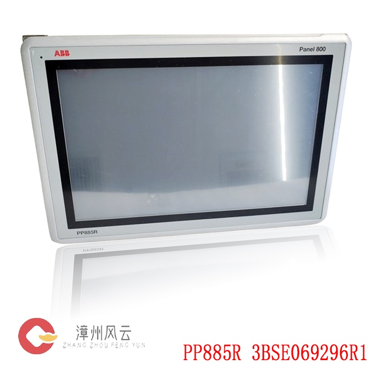
3BSE069296R1 PP885R
3BHE041626R0101 PDD405A101
3BSE003387R1 SA161
1KHW001356R0004 P4RX
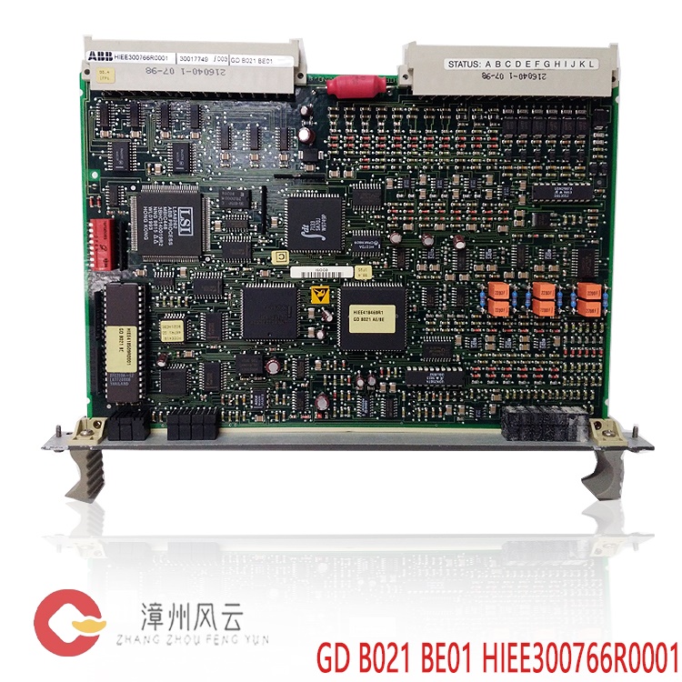
HIEE300766R0001 GD B021 BE01
3BHE020455R0001 PPD113
PPD103B101 3BHE020455R0101
3BHE020455R0101 PPD103
3BHE039724R0E41 PPD513
PVS800-57-1000KW-AUX 3AUA0000139720
PVS800-57B X51...55 3AXD50000044934
PVS800-57B X10 3AXD50000044926
More......

Address
Room 205, Office Building, No.1 Chaoyang North Road, Longwen District, Zhangzhou City, Fujian Province
fengyunfadacai@qq.com
Sales consultant
Miss.Green
+86 15860249102