
.jpg)
.jpg)
It serves as the core Control Hub—also known as the drive master control unit—for the ACS8000 high-voltage, high-power variable frequency drive system. Acting as the real-time control center for the entire high-voltage drive system, it coordinates power units, fiber-optic communications, motor control algorithms, and protection logic, while managing data exchange with the supervisory DCS/SCADA system. Equipped with a high-speed processor, it executes vector control or Direct Torque Control (DTC) algorithms to calculate PWM pulse commands in real time for transmission to the various power units, while simultaneously executing system protection logic (covering overcurrent, overvoltage, ground fault, overheating, and runaway protection).
Many products are not yet listed online; please contact us for more information.
If the product model differs from the displayed image, the model number takes precedence. Please contact us for specific product photos; we can arrange for warehouse staff to take and verify them.
We operate 76 shared warehouses globally, so it may sometimes take a few hours to provide an accurate response; we appreciate your understanding. Rest assured, we will address your inquiries as quickly as possible.
PDD405A101 3BHE041626R0101
Alternative Names:
Excitation Control Unit PDD405A101 3BHE041626R0101
PDD405A101 3BHE041626R0101 Fieldbus Coupler Module
Excitation Control Center PDD405A101 3BHE041626R0101
I. Operating Principle
The PDD405A101 3BHE041626R0101 functions essentially as a master control hub featuring real-time multi-core control and distributed fiber-optic communication:
Signal Acquisition Layer: Collects voltage, current, temperature, and IGBT status data from various power units via fiber-optic links; simultaneously acquires digital and analog signals from motor-side encoders, stator voltage/current sensors, circuit breakers, and disconnect switches. The fiber-optic solution avoids strong electromagnetic interference from the high-voltage side and ensures complete high-low voltage isolation.
Real-time Computing Layer: Features a built-in high-speed processor running vector control or Direct Torque Control (DTC) algorithms; calculates PWM pulse commands in real-time and transmits them to individual power units; simultaneously executes system protection logic (overcurrent, overvoltage, ground fault, overheating, and runaway protection).
Communication Scheduling (Core Hub Function): Acts as the master node for the internal fiber-optic network of the high-voltage variable frequency drive system; polls and synchronizes all power units to ensure strict synchronization of pulse timing across multiple units; provides industrial bus interfaces for data exchange with DCS, local HMI, and supervisory monitoring systems. Diagnostics and Status Management: Performs continuous periodic self-checks on the health of hardware links, fiber optics, power supplies, and power units; captures fault waveforms and event logs upon failure, triggering a shutdown or alarm.
Simplified Concept: It acts as the "brain" of the high-voltage variable frequency drive (VFD) and an internal fiber-optic network switch; it simultaneously collects status data from all units, issues unified control pulses, and handles external communications.
II.
Application Areas
Primarily paired with ABB ACS8000 series medium/high-voltage, high-power VFDs for speed control applications involving high-power rotating equipment:
Power Industry: Boiler induced-draft fans, forced-draft fans, primary air fans, and circulating water pumps; power plant auxiliary equipment and gas turbine starting motors.
Oil, Gas, and Chemicals: Large compressors, feedstock pumps, and circulation pumps; high-power motor drives for offshore platforms.
Metallurgy: Main drive fans; high-power auxiliary pumps and fans for rolling mills.
.jpg)
Cement and Mining: Main drives for large kilns, raw material mills, and large exhaust fans.
Marine Propulsion: High-power propulsion motors and VFDs for shipboard auxiliary power systems (high-power marine drive systems).
Suitability: Ideal for critical equipment characterized by high motor power, high voltage ratings, stringent speed/torque control precision requirements, high levels of on-site EMI (electromagnetic interference), and the need for continuous, long-term operation.
III.
Usage Instructions
1. Hardware Installation
Installed in the main control rack of the high-voltage VFD control cabinet using a standard rack-mount configuration; powered by a dedicated redundant 24VDC power supply module.
Fiber-Optic Connection: Distinguish between transmit and receive fibers and connect them one-to-one to the corresponding fiber-optic interfaces on each power unit; strictly adhere to the manual regarding fiber bend radius—sharp bending or kinking is prohibited. External signal wiring: Single-point grounding for shielded cables carrying analog, DI/DO, and encoder signals; communication bus (Ethernet/Profibus) wiring in accordance with DCS specifications.
Pre-power-up hardware checks: Verify fiber-optic link integrity, shield grounding, and terminal tightness; confirm isolation between high-voltage and control circuits.
2. Software Configuration
Use ABB DriveWindow/ACS8000 engineering software to establish a communication connection with the PDD405A101 3BHE041626R0101 unit.
Hardware configuration: Configure the number of power cells, motor nameplate parameters, encoder type, and protection thresholds.
Control mode configuration: Select DTC or vector control; configure speed loop and torque loop parameters; configure external control sources (Local/Remote DCS).
Protection logic configuration: Set protection actions (alarm, load reduction, trip) based on process requirements.
Download the program and perform no-load testing: Test fiber-optic links, verify I/O points, and conduct motor no-load trial runs while monitoring waveforms, timing sequences, and status logs.
3. Routine Operation
Issue start/stop commands and speed setpoints via the local HMI or DCS; the module transmits real-time data on speed, current, cell status, and fault information.
During the O&M phase, use engineering software to retrieve event logs and waveform recording data for fault analysis.
IV.
Problems Solved
High-precision speed regulation for high-power, high-voltage motors: Achieves smooth speed regulation and precise torque control for high-power motors, replacing hydraulic couplings and valve throttling, thereby significantly reducing energy consumption for fans and pumps.
Synchronization challenges for multiple power cells: High-voltage variable frequency drives utilize multiple power cells connected in series; the PDD405A101 3BHE041626R0101 acts as a central hub to synchronize timing, ensuring synchronized cell output and preventing voltage imbalance among cells. High/low-voltage isolated communication in strong electromagnetic environments: Uses internal fiber-optic communication to isolate strong EMI caused by high-voltage IGBT switching, preventing data errors and packet loss associated with standard copper cabling.
Unified system-wide protection and fault diagnosis: Centralized monitoring of all units and motor status; rapid fault location identification and waveform recording upon failure, reducing downtime for troubleshooting.
.jpg)
System integration and interfacing: Standardized industrial bus interfaces facilitate seamless connection with power plant or chemical plant DCS and SCADA systems, enabling remote monitoring and interlocking control.
V.
Product Advantages
Deterministic real-time control: Features a hardware-based real-time kernel with short control cycles; the DTC (Direct Torque Control) algorithm ensures rapid dynamic response and minimal motor torque ripple, making it suitable for shock loads.
Fiber-optic distributed hub architecture: Units communicate via fiber optics, offering exceptional interference immunity; supports derated operation in the event of a single power unit failure (depending on configuration), thereby enhancing system availability.
Integrated comprehensive diagnostic system: Built-in monitoring points, fault waveform recording, and event sequence logging; supports remote diagnostics to minimize on-site downtime.
High-reliability industrial hardware design: Wide operating temperature range; circuit boards feature built-in overvoltage, overcurrent, and over-temperature protection; supports redundant main control power supply configurations to meet continuous operation requirements for critical equipment.
Strong system scalability: Flexible adjustment of the number of power units to accommodate motors of various voltage ratings; multi-protocol external interfaces ensure compatibility with mainstream control systems.
VI.
Precautions
Installation and Wiring
Fiber-optic cables are fragile; maintain a minimum bending radius of ≥30mm during installation and maintenance. Clean the end faces when connecting or disconnecting fiber-optic connectors to avoid oil or dust contamination, which could otherwise cause packet loss or trigger fiber-optic fault alarms.
Route control cables and power cables separately; ground shielded cables at a single point only, as multi-point grounding can introduce ground loop interference. Module Operating Environment: Keep the cabinet dust-free, maintain the temperature between 0°C and 60°C, and prevent condensation; in humid or dusty environments, enhance cabinet air conditioning and dehumidification.
Commissioning
Strictly prohibit hot-swapping fiber optics and modules while powered on: hot-swapping causes fiber link interruptions, triggers immediate tripping of the high-voltage VFD, and can damage optical transceiver chips.
Motor parameters must be entered accurately according to the nameplate; improper parameter settings can lead to current oscillation, torque instability, or even protective shutdowns.
Perform no-load testing before applying a load; when applying a load, increase it gradually while monitoring unit balance to prevent unit voltage deviation.
Operation and Maintenance
Routine Inspections: Check module indicator status, fiber optic end-face cleanliness, and cabinet fan/cooling performance; regularly back up control programs and parameters.
Fault Handling: If a unit alarm occurs, prioritize checking the module's built-in fault log; do not repeatedly force a restart, as this could escalate the fault and damage the power unit.
Spare Part Replacement: After replacing the PDD405A101 3BHE041626R0101 module, you must re-download the project parameters and verify the fiber optic numbering sequence; reversing the sequence will result in communication failure.
Safety: The module is a control component of a high-voltage drive system; maintenance requires power-off, voltage verification, and lockout/tagout procedures. Work should only commence after the high-voltage side has been discharged.
Compatibility
The PDD405A101 3BHE041626R0101 is a dedicated master control hub for the ACS8000; it is not interchangeable with the ACS6000 or low-voltage ACS800 series drives. The firmware version must match that of the ACS8000 power unit assembly; version mismatches will cause communication errors.
Recommended
related products:
FCU400-IR
ABB
3BSE003387R1
SA161
1KHW001356R0004
P4RX
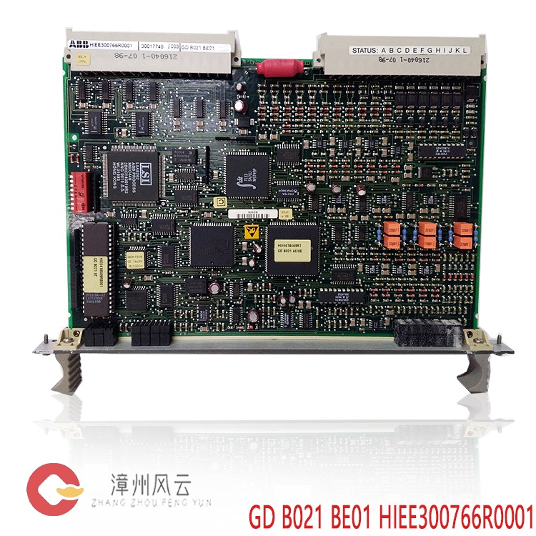
HIEE300766R0001
GD B021 BE01
HIEE300766R0001
GDB021BE01
3BHE020455R0103
PPD103B103
PPD512A10-150000
3BHE040375R1023
PPD512A10-454000
3BHE040375R103E
PPD513AOC-100440
3BHE039724R0C3D
PPD517A3011
3BHE041576R3011
3BHE039724R0C3D
PPD513AOC-100440
3BHE025541R0101
PCD231B101
3BHE032025R0101
PCD235A101
3BHE022293R0101
PCD232A
3BHE028915R0101
PCD237A101
3BHE057901R0101
PCD235C101
3BHE041343R0102
PCD530A102
More......
.jpg)
.gif)
Address
Room 205, Office Building, No.1 Chaoyang North Road, Longwen District, Zhangzhou City, Fujian Province
fengyunfadacai@qq.com
Sales consultant
Miss.Green
+86 15860249102