.gif)
.jpg)
The PEC control board generates PWM trigger commands and transmits them to the gate control unit via optical fiber. Fiber-optic transmission ensures complete electrical isolation between the control and power stages and provides immunity against strong electromagnetic interference from 6/12-pulse rectifier switching. On-board level shifting and power amplification produce standard gate drive pulses—+15V for turn-on and -8V for turn-off—with a peak current of at least 3A per channel, ensuring rapid charging and discharging of the gate capacitance and crisp switching performance.
All products on this site are specialized items subject to fluctuating market prices.
Actual pricing is based on the quote provided by customer service; the listed prices are not final.
Please confirm the model, product details, and price with customer service before placing an order.
Please contact customer service for details regarding available stock.
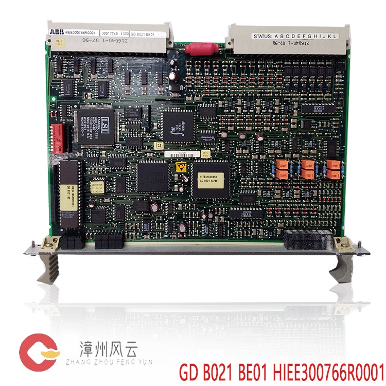
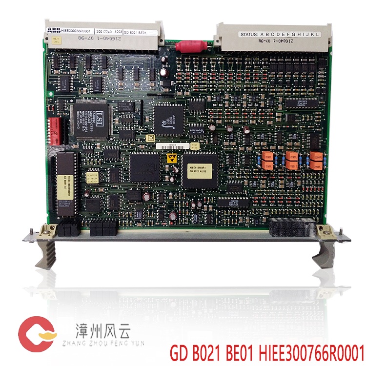
GDB021BE01 GD B021 BE01 HIEE300766R0001
Alternative Names:
Gate Drive and Protection Unit GDB021BE01 GD B021 BE01 HIEE300766R0001
GDB021BE01 GD B021 BE01 HIEE300766R0001 Gate Drive Unit
Gate Drive and Protection Unit GDB021BE01 GD B021 BE01 HIEE300766R0001
GDB021BE01 GD B021 BE01 HIEE300766R0001 is an ABB Gate Control Unit (Gate Drive and Protection Unit)—not a building access control device; "gate" here refers to the gate terminal of power semiconductors (IGBT/IGCT). It is installed within the power unit of ABB ACS6000 medium-voltage drives (3–27 MVA) and is also used in high-power systems such as DC drives and SFC (Static Frequency Converter) units. It sits between the control layer (PEC control board, e.g., GFD563A101) and the power layer (IGBT/IGCT power devices), with one unit paired to each power device.
I.
Principle
Core concept: It takes low-power PWM commands from the control board, isolates and amplifies them into high-current pulses capable of driving the IGCT/IGBT gate, while simultaneously monitoring device status in real-time to safely shut down the device within microseconds in the event of a fault. This process involves four steps:
Command Reception: The PEC control board generates PWM trigger commands and transmits them to the gate control unit via fiber optics. Fiber optic transmission ensures complete electrical isolation between the control side and the power side, providing immunity against strong electromagnetic interference from 6/12-pulse rectification switching. Isolation and Amplification: Level shifting and power amplification are performed on-board, outputting standard gate drive pulses of +15V (turn-on) and -8V (turn-off). The single-channel peak current is at least 3A, ensuring rapid charging/discharging of the gate capacitance and crisp switching action.
Real-time Protection: The VCE saturation voltage drop is continuously monitored while the device is conducting. If a short circuit or overcurrent causes an abnormal rise in VCE, the board triggers a soft turn-off or hard lockout within microseconds to prioritize the safety of the power device—the board's response speed is a critical factor in preventing IGBT failure (explosion).
Fault Feedback: Following a protection event, the fault status is transmitted back to the main controller via dry contacts and fiber-optic signals, triggering system alarms or shutdowns.
Key Specifications: Auxiliary power supply 24V DC (±10%); isolation between control and power sides ≥ 2500V AC; operating temperature -20 to +60°C; dimensions 206×37×276mm; weight approx. 0.42kg; IP20 cabinet protection rating; on-board LEDs for Power, Run, and Fault status.
II.
Application Areas
ACS6000 Medium-Voltage Variable Frequency Drive (VFD): High-power drive systems; each IGCT power device is paired with a dedicated gate control unit.
SFC (Static Frequency Converter): Variable frequency power supply for starting gas turbines and pumped-storage units.
DC Drive Power Units: High-power DC drive cabinets.
.jpg)
Typical Load Industries: Medium-voltage motor applications including metallurgical rolling mills, mining hoists/conveyors, cement mills, oil and gas compressors, power plant auxiliary equipment, and marine propulsion.
III. Precautions
High Voltage Hazard: The power side operates at medium voltage (kV range). Before inserting or removing the unit, power must be disconnected, and the DC bus must be confirmed fully discharged and grounded; strictly follow the procedures outlined in the service manual.Electrostatic Protection: When handling precision circuit boards, wear an anti-static wrist strap and work on an anti-static workbench.
Fiber Optic Handling: Do not bend connectors excessively; keep end-faces clean; check the optical link first when troubleshooting.
Version Matching: When replacing spare parts, verify that hardware/firmware versions match the master controller configuration; re-run the commissioning procedure after board replacement.
Counterfeit Prevention: Ensure the part is a genuine original; request records of the power-on self-test and functional verification.
IV.
Operating Procedures / Usage Instructions
Installation and Wiring: Insert the board into the corresponding slot on the power unit and secure it; connect the PEC-side fiber optics and IGCT/IGBT gate leads; connect the 24V DC auxiliary power supply; verify that wiring matches the manual's diagrams.
Power-on Self-test: Observe the LEDs after applying auxiliary power—normal status is indicated by the power light being on, the run light flashing normally, and the fault light being off; if the fault light is on, troubleshoot based on the fault code.
System Commissioning: Issue PWM commands via the ACS6000 commissioning software or control panel; monitor drive output and feedback; proceed to load operation after confirming there are no fault messages.
.gif)
Replacement Procedure: Power off → Discharge/Ground → Remove old board → Install new board → Restore wiring → Power-on self-test → Perform IGCT gate function test per manual → Commission into service.
Routine Maintenance: Periodically inspect LEDs, fiber optic connections, board mounting, and cooling air ducts; record fault messages for trend analysis.
Recommended
related products:
3BHE020455R0001
PPD113
PPD103B101
3BHE02384R2630
3BHE020455R0101
PPD103
PPD513
A0E-110110 3BHE039724R0E41
PPD115A102
3BHE017628R0102
3BHE030410R3011
PPD117A3011
3BHE020455R0103
PPD103B103
PPD512A10-150000
3BHE040375R1023
PPD512A10-454000
3BHE040375R103E
PPD513AOC-100440
3BHE039724R0C3D
PPD517A3011
3BHE041576R3011
3BHE039724R0C3D
PPD513AOC-100440
3BHE025541R0101
PCD231B101
3BHE032025R0101
PCD235A101
3BHE022293R0101
PCD232A
3BHE028915R0101
PCD237A101
3BHE057901R0101
PCD235C101
3BHE041343R0102
PCD530A102
More......
.jpg)
.jpg)
Address
Room 205, Office Building, No.1 Chaoyang North Road, Longwen District, Zhangzhou City, Fujian Province
fengyunfadacai@qq.com
Sales consultant
Miss.Green
+86 15860249102