.jpg)
.jpg)
Designed for use in modern DEIF generator set protection and power management systems, this optical power measurement instrument utilizes optical fibers instead of traditional copper signal cables to ensure highly interference-resistant signal transmission. It comprises a photodetector, a wavelength-selective filter circuit, a signal amplification unit, an analog-to-digital conversion module, a microprocessor, and a display unit. The main control unit performs calculations and outputs optical power readings in dBm (with certain modes allowing conversion to linear power in mW); when used with an external stable light source, it calculates fiber-optic link insertion loss—derived from the difference between transmitted and received power—to evaluate attenuation caused by fusion splices, connectors, and fiber bends.
All products on this website are specialized items subject to fluctuating market prices.
Please refer to the customer service quotation for specific pricing, as the listed prices are not final.
Before placing an order, please confirm details such as the model, product specifications, and price with customer service.
New units are available for sale; please contact customer service for details.
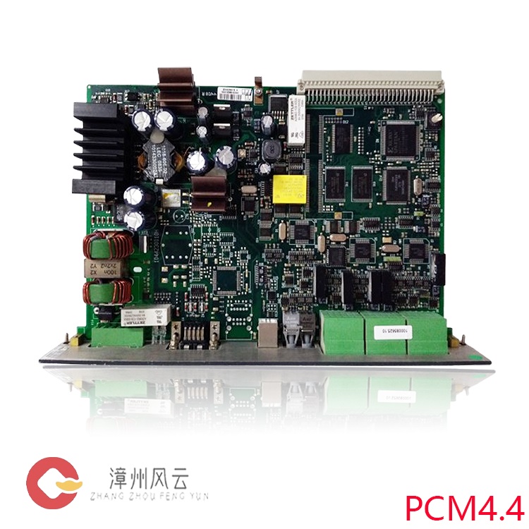
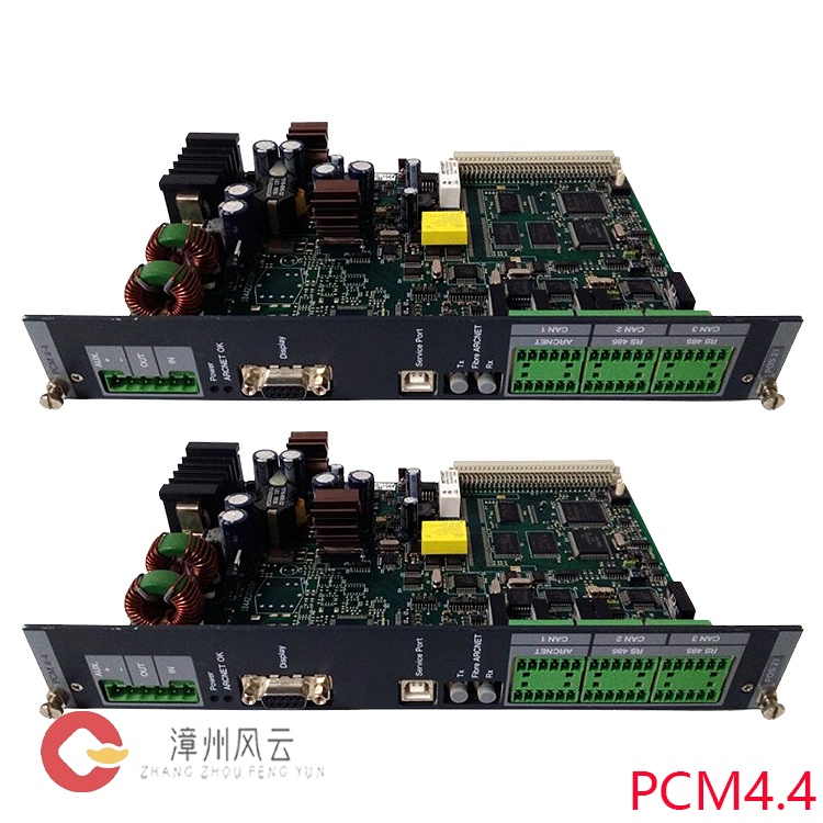
1044500030E
Alternative Names:
Optical Power Meter 1044500030E
1044500030E Dual Optical Power Meter Module
Optical Network Monitor 1044500030E
I. Product Overview
The DEIF 1044500030E portable optical power meter is a specialized instrument designed for measuring optical power in fiber-optic communication links within power plants, offshore facilities, and marine power systems. Modern DEIF generator protection and power management systems extensively utilize fiber optics—replacing traditional copper signal cables—to achieve highly interference-resistant signal transmission. The 1044500030E is used for on-site measurement, acceptance testing, and troubleshooting of received optical power and link insertion loss; it is the standard test tool for the installation, commissioning, and routine maintenance of DEIF fiber-optic-based generator protection and power management systems.
II.
Working Principle
The 1044500030E operates based on the principle of photoelectric conversion to measure optical power. It consists of a photodetector, a wavelength-selective filter circuit, a signal amplification unit, an analog-to-digital conversion module, a microprocessor, and a display unit.
Optical Signal Reception: The optical signal output from the fiber under test enters the instrument's optical input port via an adapter connector and strikes the built-in InGaAs photodetector. The InGaAs detector is optimized for wavelengths commonly used in power industry fiber-optic communications (such as 1310nm and 1550nm) and is matched to the emission spectrum of DEIF fiber-optic interface modules.

Photoelectric Conversion: Incident photons excite the semiconductor material to generate photocarriers, linearly converting the optical signal into a weak electrical current signal; the magnitude of the output current is directly proportional to the incident optical power. Signal Conditioning and Acquisition: Weak photocurrents are processed by a low-noise amplification circuit, and an ADC chip converts the analog electrical signals into digital data. The instrument features built-in calibration curves (NIST-traceable); it automatically selects the appropriate calibration coefficients based on the chosen wavelength to compensate for variations in the detector's wavelength response.
Data Processing and Display: The main control unit performs calculations and outputs optical power readings in dBm (with linear power conversion to mW available in certain modes). When used with an external stabilized light source, it calculates fiber link insertion loss via the formula "Transmitted Power − Received Power," allowing for the assessment of attenuation caused by fusion splices, connectors, and fiber bends.
Wavelength Calibration Mechanism: The instrument includes multiple factory-calibrated wavelength points. Engineers can manually select the operating wavelength to match the specific fiber-optic communication system in use, thereby eliminating response deviations across different wavelengths and ensuring measurement accuracy.
Note: The 1044500030E measures received optical power only; for complete link loss testing, it must be paired with a compatible DEIF stabilized light source (OLS).
III.
Core Product Advantages (Targeting the Power and Marine Industries; Distinct
from General-Purpose Telecom Optical Power Meters)
1. Specifically Optimized for DEIF Power System Fiber-Optic Networks
While standard optical power meters are designed for telecommunications networks, the 1044500030E features calibrated wavelengths and optical interfaces specifically matched to the fiber-optic communication ports of DEIF generator protection and power management modules. When commissioning DEIF fiber-optic differential protection or multi-unit parallel synchronization links, the measurement data aligns perfectly with the devices' internal optical reception thresholds, preventing the assessment errors often associated with general-purpose instruments.2. Wide operating temperature range and high reliability; suitable for harsh marine and industrial power plant environments
Wide operating temperature range adapts to temperature fluctuations in engine rooms and electrical distribution rooms;
Vibration-resistant and EMI-shielded design ensures accurate readings unaffected by electromagnetic interference from power equipment in generator rooms characterized by strong magnetic fields and high currents;
Low power consumption and long battery life support extended on-site testing; features an auto-shutdown function to prevent power drainage if the device is left on.
3. High measurement accuracy with traceable calibration
High measurement accuracy within typical operating ranges allows for the detection of minute changes in link attenuation; factory calibration is traceable, meeting documentation requirements for project acceptance by classification societies (DNV, ABS, LR) and third-party power plant inspections, with test reports holding official compliance validity.
4. Simple operation; engineer-friendly design
Requires only two core actions—wavelength selection and reading—eliminating the need for complex configurations; large, backlit LCD screen ensures readability in dimly lit engine rooms; supports interchangeable adapter caps (FC/SC/ST) compatible with various DEIF module fiber connectors, enabling quick swaps and reducing the risk of fiber end-face contamination.
5. Lightweight and portable design
Compact and lightweight, making it easy for engineers to carry on board ships or to power plant sites; includes a protective casing to guard against accidental impacts; fits into the DEIF system commissioning toolkit.
6. Rapid fault localization capabilities
By
measuring received optical power, the device quickly identifies common fiber
link issues—such as fiber breaks, dirty end-faces, poor flange contact,
excessive fiber bending, excessive splice loss, and optical power degradation in
the transmitter module—significantly reducing troubleshooting time for
fiber-optic protection systems on ships and in power plants.
IV. Typical Application Scenarios
1. Installation and Commissioning of New Projects (Marine / Shore Power / Industrial Power Plants)
After completing the wiring for DEIF fiber-optic power management and generator differential protection systems, use the 1044500030E to test the received optical power of the fiber link segment by segment. Record link losses and complete construction acceptance by verifying that the fiber link meets the device's minimum received optical power threshold; this prevents protection malfunctions or communication interruptions upon power-up. Typical scenarios include fiber-optic synchronization between multiple generators and generator fiber-optic differential protection loops.
2. Periodic Preventive Maintenance
During annual marine inspections or power plant overhauls, periodically record optical power on fiber communication links to establish baseline data. Compare current readings against historical baselines to anticipate issues such as fiber aging, end-face contamination, or gradual connector attenuation. Addressing these problems before failure occurs ensures the continuous, reliable operation of the unit's protection system.
3. Troubleshooting and Emergency Repair
When a DEIF unit controller reports a fiber communication interruption or a fiber link alarm, the 1044500030E serves as the primary troubleshooting tool. It allows for segmented measurement of received optical power to pinpoint the faulty section and distinguish the root cause—whether it is a fiber link issue or damage to the controller's internal optical transmitter/receiver module—thereby minimizing downtime for emergency repairs.
.jpg)
4. Spare Parts and Maintenance Testing
When servicing DEIF fiber-optic interface cards, the 1044500030E is used to measure the output power of the card's optical transmitter port, assess the aging of optical transmission components, and determine whether the module requires replacement.
5. Classification Society Acceptance and Project Handover Testing
On-site measurement data can serve as acceptance documentation, satisfying the testing and verification requirements of classification societies (such as DNV and ABS) regarding fiber-optic links in marine power protection systems.
Recommended
related products:
SCM-B
1044220110F
SCM-A
1044220100F
DEIF
APU-4
AGI
115-2 1241000013A
AGI
107-2 1241000011A
LCD
1241000001A | AGI-107
1241000014A
AGI 110-2
DEIF
85951.7 ACV-3TR
2044230010
G PCM 4.1
DEIF
IOM230
DEIF
MTR-2F-215
DEIF
XDI192-NAVI
AGC
252 1044540020F
VTR-3
SERNO.05083
W0CH
5421 GPC/GS
TAX
312DG 407696.10
DUAL
400056237.60
DEIF-827.41
100023045
DEIF
HAS-2N
1044220140E-CRM-1
POS
AOM-1
1044220150C
More......
Address
Room 205, Office Building, No.1 Chaoyang North Road, Longwen District, Zhangzhou City, Fujian Province
fengyunfadacai@qq.com
Sales consultant
Miss.Green
+86 15860249102