
Technical articles
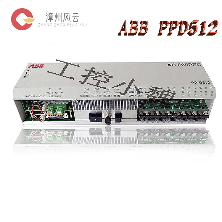
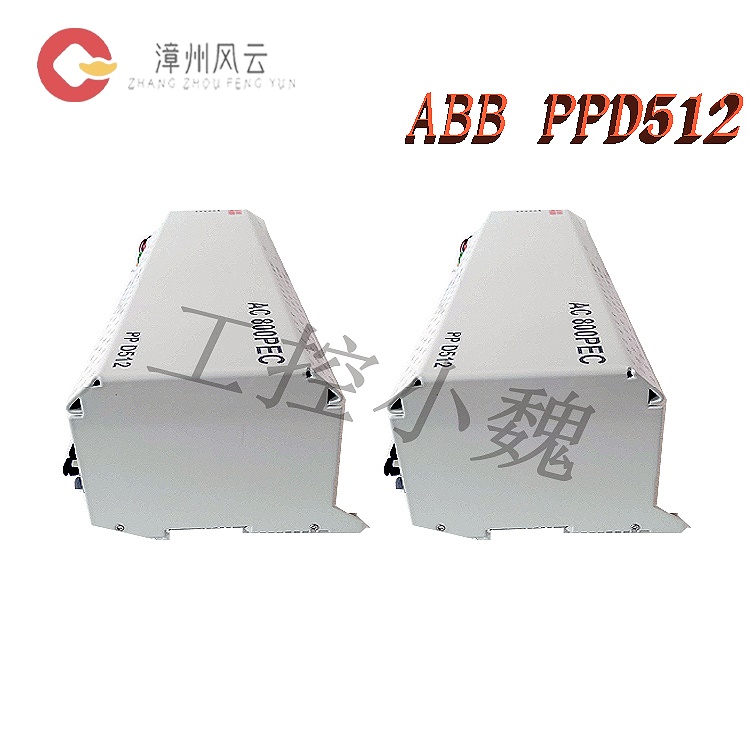
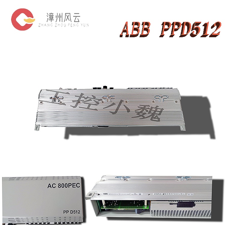
How to install ABB AC 800PEC Control System PPD113B01-25-111000 3BHE023784R2530?
Date: Nov 23, 2025 Views: 665
Hardware Installation Steps
Mechanical Installation
Rail Mounting: The module uses a standard DIN rail for mounting, measuring approximately 150×100×50mm, weighing 1.5kg, with an IP20 protection rating, suitable for integration within control cabinets.
Backplane Connection: The processor, power supply, and communication modules are mounted via an AC 800PEC BP backplane, supporting up to 6 optical modules (such as S800 I/O modules) connected via fiber optic links, with a maximum length of 305 meters.
Heat Dissipation and Protection:
The module employs a natural cooling design. Ensure good ventilation within the control cabinet and avoid high-temperature environments (operating temperature -40°C to +70°C).
In humid, corrosive environments or explosion-proof areas, a protective enclosure conforming to IP67/NEMA 4X standards must be selected, and industrial safety standards such as API 670 must be followed.
Module Integration
Processor Module: Based on a 750 MHz RISC processor, integrating a 64-bit IEEE floating-point unit, 64MB ECC memory, and 16MB Flash, supporting high-speed control cycles (as low as 100μs).
I/O Expansion: Connects to S800 series I/O modules via fiber optic link, supporting 16 digital inputs/8 digital outputs, compatible with EnDat, SSI, and other encoder protocols.
Electrical Connection Specifications
Power Supply Configuration
Input Requirements: 24V DC ±15% (18-30V), supporting redundant power supply design to ensure continuous operation.
Grounding Specifications: Single-point grounding, with the shielding layer grounded at a single point to suppress electromagnetic interference; avoid parallel wiring with power cables.
Communication Interface
Network Configuration: Supports protocols such as EtherCAT, PROFINET, CANopen, and Modbus; adapts to various fieldbus types via the AnyBus-S interface.
IP Address Settings: Configure the controller's IP address (e.g., 192.168.125.5) using Control Builder M software or IPConfig tool, ensuring it's on the same network segment as the computer, with a subnet mask of 255.255.255.0.
Connection Method: Connect the computer and controller via Ethernet (RJ45) or RS232 serial port (e.g., TK212 cable) for program download and debugging.
Signal and Communication Wiring:
I/O modules connect to the backplane via fiber optic or Ethernet interfaces, supporting analog (4-20mA/0-10V), digital (24V DC), and high-speed pulse signal input/output.
Communication modules support RS485, ModBus RTU, CAN bus, and Ethernet protocols (e.g., Modbus TCP, EtherNet/IP). Protocol type and baud rate must be configured according to system requirements.
Grounding and Shielding: Single-point grounding principle; the shielding layer should be grounded at a single point to suppress electromagnetic interference and avoid parallel wiring with power cables.
Software Configuration Process
Engineering Tools
Development Environment: Use Control Builder M or System 800xA platform for system configuration, program writing (supports IEC61131-3 language), and offline simulation.
Program Download: The compiled program is downloaded to the controller via Ethernet or serial port, supporting real-time monitoring and fault diagnosis.
System Configuration
Hardware Configuration: Configure the physical connections of the backplane, processor, power supply, and communication modules in the software.
Protocol Matching: Select a communication protocol compatible with the controller (e.g., Modbus TCP) and configure I/O module parameters (e.g., analog input range, digital output type).
3. Software Configuration and Programming
Engineering Tool Installation:
Install ABB Control Builder M or System 800xA platform for system configuration, program writing, and debugging. Supports IEC61131-3 standard programming (e.g., ladder diagrams, structured text).
Install MATLAB/Simulink and Real-Time Workshop plugins to achieve model-based design and control algorithm deployment.
System Configuration Steps:
Hardware Configuration: Scan the backplane hardware using engineering tools to identify the installed processor, I/O, and communication modules. Configure module parameters (e.g., I/O address, communication protocol).
Program Development:Write control logic (e.g., PID algorithm, motion control algorithm) to support multi-axis linkage and high-speed dynamic response (control cycle ≤ 1ms).
Communication Configuration: Set network parameters (IP address, subnet mask) and configure communication protocols with the host computer (e.g., SCADA system) or third-party devices (e.g., PLC, HMI).
Program Download and Debugging:
Download the program to the controller via Ethernet or serial port. Use online monitoring to view I/O status, variable values, and alarm information in real time.
Analyze ERR/BUS alarms using fault diagnosis tools to locate hardware or communication faults. Supports remote diagnosis and firmware updates.
Maintenance and Expansion Recommendations:
Regular Maintenance:
Cleaning and Inspection: Regularly clean dust from module surfaces, check connectors and cables for integrity, and ensure good heat dissipation.
Performance Monitoring: Monitors processor load, memory usage, and communication status using software tools to promptly identify and resolve anomalies.
Expansion Capabilities
Module Expansion: Connects more I/O modules or expansion units via fiber optic links to adapt to the needs of control systems of different sizes.
Firmware Updates: Updates controller firmware using software tools to fix vulnerabilities or improve performance.
Safety Specifications and Compatibility
Safety Standards
Protection Functions: Supports Safe Torque Stop (STO) and overcurrent/overvoltage protection, complying with industrial safety standards such as API 670.
Explosion-proof Certification: Adapts to explosion-proof certified models (e.g., -CN suffix), meeting the requirements for use in hazardous areas.
Compatibility Verification
Device Collaboration: Compatible with ABB ecosystem devices (e.g., 3500/40M monitoring modules) and third-party devices (e.g., Bently Nevada sensors); interface standards and protocol compatibility must be verified.
Software Compatibility: Ensures compatibility between the Control Builder M or System 800xA platform version and the controller firmware.
In summary, through standardized hardware installation, electrical connections, software configuration, and maintenance processes, the ABB AC 800PEC PPD113B01-25-111000 module can be ensured to operate efficiently and stably, meeting the high reliability requirements of fields such as industrial automation and energy management.
Related product recommendations:
ABB EL3020
ABB EL3040
3AUA0000036521 RDCU-12
3AUA0000036521 RDCU-12C
64607901 RDCU-02
64607901 RDCU-02C
3AUA000110430 BCU-12
3AUA000110429 BCU-02
HESG440295R2 FC95-22
3BHE020356R0101 GFD212A
3BHE020357P201 GFD212A
3BH022294R0103 GFD233A103
3BHE022294R0103 GFD233A103
3BHE046836R0101 GFD563A101
3BHE046836R0102 GFD563A102
3BHE020P201ARNDA PDD200A101
3BHE025335R1121 PDD205A1121
3BHE037649R0101 PDD500A101
3BSX105983-100 PFCL201CE 10KN
3BSX802939-108 PFCL201CE 50KN
3BSE028140R0020 PFEA111-20
More......
RELATED ARTICLE
Address
Room 205, Office Building, No.1 Chaoyang North Road, Longwen District, Zhangzhou City, Fujian Province
fengyunfadacai@qq.com
Sales consultant
Miss.Green
+86 15860249102