

Technical articles
How to set up the ABB ACS6000 medium voltage drive system phase module S-073H 3BHB009884R0001?
Date: Oct 18, 2025 Views: 5886
Setting up the ABB ACS6000 medium-voltage drive system phase module S-073H 3BHB009884R0001 requires a multi-faceted approach, encompassing hardware installation, software configuration, parameter tuning, and communication connections. The specific steps are as follows:
1. Hardware Installation and Physical Configuration
Modular Installation: The module utilizes a modular design and supports hot-swappable functionality. During installation, ensure that the module is fully aligned with the rack slot, securely fastened with a mounting bracket, and connect the power supply, signal cables, and communication interfaces (such as Ethernet, Modbus TCP, and PROFINET). The module itself has an IP20 protection rating and requires a cabinet with higher protection (such as IP54).
.jpg)
Electrical Connections: The input voltage range is 6.0–6.9 kV, requiring a redundant power supply module. Ensure the correct phase sequence when connecting the output to the motor or load. An external cooling system (air or water) is required to ensure unobstructed heat dissipation.
Grounding and Protection: Use equipotential single-point grounding, with lightning protection grounding separated from the system ground. To prevent electromagnetic interference, filter the signal lines and separate the power and signal wiring.
2. Software Configuration and Parameter Settings
Programming Tools: Use ABB Control Builder M or Automation Builder software for parameter configuration and program development. Supports IEC 61131-3 and is compatible with the CODESYS environment.
Core Parameter Settings:
Motor Parameters: Enter rated voltage, current, frequency, speed, power, etc. (e.g., a 6000kW motor must accurately match the nameplate data).
Control Mode: Select V/F control, vector control, or direct torque control (DTC). DTC technology achieves millisecond-level torque response and is suitable for highly dynamic loads such as rolling mills and wind turbines.
Dynamic Parameters: Set acceleration and deceleration times (e.g., 8-12s for wind turbine acceleration and 10-15s for deceleration), overcurrent protection threshold (1.2 times the rated current), undervoltage protection value, etc.
I/O Configuration: Digital input/output channel mapping (e.g., DI: 10.24 brake signal, AI: 13 groups of 4-20mA range), and analog input and output range calibration.
Advanced Features: Enable dynamic reactive power compensation (20-100 Mvar), grid fault ride-through protection, and energy regeneration (brake energy is fed back to the grid with an efficiency of up to 92%).
3. Communication and Network Integration
Protocol Selection: Supports industry-standard protocols such as Modbus TCP, PROFINET, and Ethernet/IP. Configure the IP address (e.g., 192.168.1.10), subnet mask, gateway, and port number to ensure compatibility with host computers (e.g., PLCs, SCADA systems) or third-party devices (e.g., Siemens/Schneider equipment).
Data Interaction: Connect to HMI/SCADA systems via OPC UA or connect to domestic configuration software (e.g., KingView) via Modbus TCP. Configure register mapping (e.g., frequency settings correspond to register 40001).
Synchronization Verification: Use a network test tool (e.g., Wireshark) to check packet transmission to ensure correct protocol configuration; send test commands through DriveComposer software to verify communication stability.
4. Debugging and Optimization
No-load Test: Disconnect the load, start the inverter at 50Hz, listen for abnormal sounds, and perform an emergency stop test to verify basic functionality.
Load Test: Gradually increase the load, monitor output current, voltage, temperature, and other parameters, and adjust acceleration and deceleration times and PID parameters (such as proportional gain and integral time) to optimize dynamic performance.
Fault Diagnosis: Use built-in self-diagnostic functions (such as fault code query and logging) to locate problems. Use the LED indicators (RUN/ERR) to determine operating status; a solid red light indicates a hardware fault.
.jpg)
5. Maintenance and Safety Standards
Regular Maintenance: Check cooling system efficiency, electrical parameter fluctuations, and ground connection reliability; clean the heat sink and replace aging fans or thermal grease.
Safe Operation: Disconnect power before performing module replacement or maintenance, and avoid working with live power. Wear insulating protective equipment for high-voltage components and ensure the ground resistance is ≤4Ω.
Compatibility Verification: When integrating with third-party devices, verify communication protocol compatibility (e.g., PROFIBUS DP master configuration). Firmware upgrades must be stored via eMMC to prevent program loss during power outages.
6. Special Scenarios
Multi-Motor Collaboration: Connecting multiple motors via a common DC bus enables energy recycling (e.g., braking energy fed back to the grid), reducing energy consumption by over 15%.
Harsh Environments: For high-dust, high-corrosion environments like mining
and chemical industries, corrosion-resistant materials and coatings are used,
and sealing design is enhanced. For offshore wind power applications, lightning
protection and electromagnetic pulse protection devices are installed.
Related product recommendations:
3BHB009885R0013 S-093M
3BHB009885R0052 S-097H
3BHB009885R0063 S-093M
3BHB009885R0005 S-093H
3BHB009885R5311 S-093R
35SHY3545L0014 S-073N
3BHB009884R0021 S-073N
3BHB009885R0052 S-097H
3BHB030478R0309 S-093H
3BHB012897R0003 S-053M
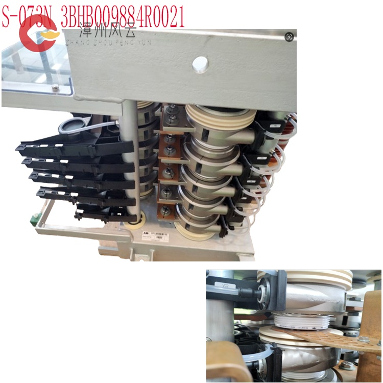
S-073N 3BHB009884R0021
3BHE041430R0001 ABB
3BHE041429R0001 ABB
3BHE041418R0001 ABB
3BHE041414R0001 ABB
3BHS393721 E01 ABB
3BHS600000 E40 ABB
3BHS606571 E49 ABB
3BHS537463 E72 ABB
3BHS600000 E87 ABB
More......
RELATED ARTICLE
Address
Room 205, Office Building, No.1 Chaoyang North Road, Longwen District, Zhangzhou City, Fujian Province
fengyunfadacai@qq.com
Sales consultant
Miss.Green
+86 15860249102