

Technical articles
ABB Important note - main circuit breaker ACS6000 GBU72 3BHE055094R0002
Date: Oct 15, 2025 Views: 4688
The main circuit breaker (MCB) is a major protection device of the drive. If a serious fault occurs in the drive, the MCB must disconnect the main power supply to the drive immediately. The main power supply must be disconnected without delay on an open or trip command from the drive to prevent hazard to the personnel and further damage to the equipment. The MCB is located on the primary side of the converter transformer.
NOTE – MCBs and protection relays are not included in the drive supply.
Typical MCBs devices
– Vacuum circuit breakers
– SF6 circuit breakers
– Fused contactors or motor control centers
Dedicated protection relay
– Transformer or drive primary cable protection (DTL)
– Transformer protection (if applicable)
– Transformer secondary cable protection (if applicable)
.jpg)
– Backing up the drive protection
Safety and protection requirements
The system integrator must ensure that the following minimum safety and protection requirements for the drive are met:
– ISO 13849-1
– IEC 60204-1
Safety and protection requirements for the MCB
The following safety requirements are also in the MCB specifications for the drive:
– MCB open and/or trip command: must be wired directly from the drive to the MCB. If you want to wire the command through a PLC or DCS system, the system must be certified to meet SIL three-level requirements and to fulfill the maximum MCB opening timing requirements. The drive must also be able to open the MCB at any time. It is not permitted to interrupt the open and/or trip command, eg, with a local-remote switch in the MCB.
– Closing control of the MCB: when the MCB is in service position, the drive must have exclusive control over closing the MCB, ie, local closing of the MCB is not permitted.
– MCB maximum opening time: cannot exceed the maximum time that is defined in the product or project-specific MCB specifications.
Typical maximum values for the drive are defined as follows:
– Maximum protection trip time: 75 ms
The maximum protection trip time is the maximum allowed breaking time (open and arcing) of the breaking device after the open command has been initiated to prevent further damage to the drive, such as diode failures.
– Maximum safety trip time: 500 ms
The maximum safety trip time is the maximum allowed time to ensure safe disconnection of the main power supply to prevent any hazard to personnel.
In order to meet the stipulated safety requirements, ABB recommends one of the following:
– MCB is equipped with 2 independent opening coils
– MCB is equipped with an opening coil and an undervoltage coil for monitoring of the control voltage
– Upstream protection coordination scheme is provided which uses the “breaker failure”
(ANSI 50BF) signal to automatically trip the upstream breaker, in case the MCB does not open.
IMPORTANT! The upstream breaker must open within the maximum safety trip time after a failure has occurred.
Power electronics and cabinet features
Drive system topology
The ACS6000 drive system consists of the following components:
– Main circuit breaker: For more information, see section 2.8, Maintenance recommendation, page 39.
– Input transformer: Required if the line voltage must be adapted to the motor voltage.
For more information, see the “Main transformer specification”.
– Drive
– Motor
Drive
The ACS6000 is a voltage source frequency converter for high-power induction and synchronous motors. The drive features a common DC bus permitting the configuration of single-motor or multi-motor solutions.
Figure 3–1 Common DC-bus principle for single motor drive (A) and multi-motor drive (B)
The drive has a flexible modular design with standard and optional cabinet units. Each cabinet unit is dedicated to a specific function
Figure 3–2 ACS6000 drive example
1) Active rectifier unit (ARU): Self-commutated, 6-pulse, 3-level voltage source inverter with IGCT technology
2) Drive control panel for local operation: Keypad with multi-language display, main supply on/off push buttons, and emergency-off push button
3) Inverter unit (INU): Self-commutated, 6-pulse, 3-level voltage source inverter with IGCT technology
4) Capacitor bank unit (CBU): DC capacitors for smoothing the intermediate DC voltage
5) Water cooling unit (WCU): Supplies deionized water for cooling the main power components
6) Terminal unit (TEU) and control unit (COU): Contains the power terminals and the control swing frame
7) Braking chopper unit (BCU), resistor braking unit (RBU) or voltage limiter unit (VLU): Optional cabinet units
8) Excitation unit (EXU): Optional cabinet unit that supplies a synchronous motor with excitation
The drive is assembled from standard and optional cabinet units. Each unit is dedicated to a specific function.
For more information on the cabinet units in your drive, see the layout drawing in “Appendix C - Mechanical drawings”.
Final drive configuration
The final drive configuration depends on the following factors:
– Required output power
– Configuration of the main power supply (input transformer or direct-to-line connection)
– Ability to recover energy (active or diode front end)
– Motor type (synchronous or asynchronous)
– Single or multi-motor application.
Active rectifier unit (ARU)/inverter unit (INU)
An ARU and INU have the same mechanical and electrical designs.
– ARU: 6-pulse self-commutated voltage source inverter that rectifies the line voltage of the supply network and maintains the DC-link voltage at a constant level irrespective of changes in the supply network.
The active 6-pulse rectifier allows for regenerative braking.
– INU: controls the 3-phase motor voltage and converts the DC-link voltage to the required AC motor voltage and frequency
The INU is a self-commutated voltage source inverter in 6-pulse, 3-level topology. To increase the drive power, 4 units can be operated in parallel on 1 motor
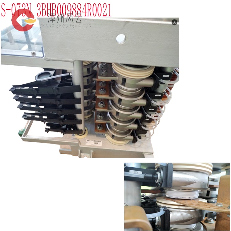
Phase module (IPS 21-24V-UL 3BHE032593R0002 S-093N 3BHB009885R0001,S-093N 3BHB009885R0021,S-093N 3BHB009885R5311,S-093N 3BHB006457R0001,S-093H 3BHB030478R0309,S-123H 3BHB030479R0512,S-073H 3BHB030477R0207,3BHB009885R0104 S-093H,3BHB009885R0063 S-093M,3BHB009885R0052 S-093H 3BHB009885R0032,3BHB009885R0031 S-093S,3BHB009885R0021 S-093N,3BHB009885R0014 S-093M,3BHB009885R0013 S-093M,3BHB009885R0004 S-093H 3BHB009885R0002 S-093H,3BHB009885R0001,3BHB009884R0204 ,S-073H 3BHB009884R0052 S-073H 3BHB009884R0022,3BHB009884R0021 S-073N,3BHB009884R0013 S-073M,3BHB009884R0004 S-073H 3BHB009884R0002 , S-073H 3BHB009884R0001,S-093N 3BHB009885R0001,S-093N 3BHB009885R0021,S-093N 3BHB009885R5311,S-093N 3BHB006457R0001,S-093H 3BHB030478R0309,S-123H 3BHB030479R0512,S-073H 3BHB030477R0207,S-093N 3BHB009885R0001,S-093N 3BHB009885R0021,S-093H 3BHB030478R0309,S-123H 3BHB030479R0512,S-073H 3BHB030477R0207)Consists of integrated gate-commutated thyristors (IGCTs), diodes and clamp capacitors. The phase modules are identical in construction for all power ratings. However, the types of semiconductors vary depending on the power rating. For this reason, it is not possible to mix phase modules for different power ratings in one unit.
Clamping circuit Protects the circuit from excessive rises in current with di/dt reactors and freewheeling diodes.
Electromagnetic compatibility (EMC) filter Protects the transformer from excessive voltage slopes
ACS6000 3BHS212794 E01
Figure 3–5 ARU/INU (A) and phase modules with IGCTs (B)
1) EMC filter
2) Control interface
3) IPS
4) Phase module
5) Diode
6) Coolant outlet
7) IGCT
8) Coolant inlet
9) Clamp capacitor
. Line supply unit (LSU)
The LSU is a 12-pulse rectifier that rectifies the AC line voltage and supplies the DC link with electrical energy. An LSU is used with input transformers and is available in various power ratings.
The LSU allows two-quadrant operation and maintains the power factor at 0.95 in the whole operating range.
To achieve 24-pulse rectification or to increase the drive power, units
with the same power rating can be operated in parallel.
Related product recommendations:
3BHB009885R0013 S-093M
3BHB009885R0052 S-097H
3BHB009885R0063 S-093M
3BHB009885R0005 S-093H
3BHB009885R5311 S-093R
35SHY3545L0014 S-073N
3BHB009884R0021 S-073N
3BHB009885R0052 S-097H
3BHB030478R0309 S-093H
3BHB012897R0003 S-053M
S-073N 3BHB009884R0021
3BHE041430R0001 ABB
3BHE041429R0001 ABB
3BHE041418R0001 ABB
3BHE041414R0001 ABB
3BHS393721 E01 ABB
3BHS600000 E40 ABB
3BHS606571 E49 ABB
3BHS537463 E72 ABB
3BHS600000 E87 ABB
More......
RELATED ARTICLE
Address
Room 205, Office Building, No.1 Chaoyang North Road, Longwen District, Zhangzhou City, Fujian Province
fengyunfadacai@qq.com
Sales consultant
Miss.Green
+86 15860249102