.jpg)
.jpg)
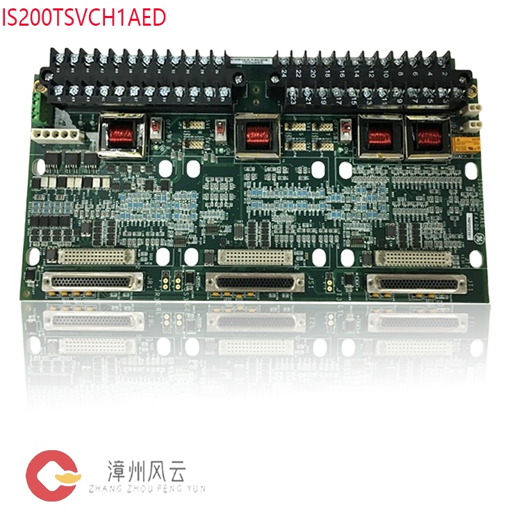
The board utilizes a low-impedance copper busbar architecture to evenly distribute the incoming 28V DC power—via independent busbars—to 24 I/O module power interfaces and 3 Ethernet switch power interfaces. A single board can simultaneously power 24 Mark VIe series I/O acquisition modules and 3 industrial Ethernet switches, achieving industry-leading power output density within a compact PCB footprint; this significantly simplifies system power cabling and reduces cabinet space requirements. It features a standard 6-pin Mate-N-Lok input connector (J1) supporting three independent 28V DC power inputs to establish a triple-redundant power architecture, while the remaining three pins serve as a common return path, accommodating the return requirements of both TMR (Triple Modular Redundancy) systems and daisy-chained power configurations. With a rated current of 13A per pin and an insulation voltage rating of up to 600V, the board fully meets industrial power capacity and electrical safety standards, ensuring that a failure in any single input channel does not compromise overall power continuity.
Many products have not yet been listed online; please contact us for more information.
If the product model differs from the displayed image, the model number takes precedence. Please contact us for specific product photos; we can arrange for warehouse staff to take and provide confirmation images.
We operate 76 shared warehouses globally, so it may sometimes take a few hours to provide you with an accurate response; we appreciate your understanding. Rest assured, we will address your inquiries as quickly as possible.
IS200WROBH1ABA
Alternative Names:
PCB Module IS200WROBH1ABA
IS200WROBH1ABA Digital Drive Board
I/O Group Power Distribution Card IS200WROBH1ABA
I. Product Overview
The
GE IS200WROBH1ABA is a High-Density Power Distribution Board
(JPDH board) designed specifically for the General Electric
(GE) Speedtronic Mark VIe series control system, serving as a
core component of the system's power architecture. It primarily handles
centralized DC power distribution, fault protection, and system expansion,
providing stable and reliable power to critical components such as I/O
acquisition packs and Ethernet switches. It acts as a vital hub connecting the
power supply source to field data acquisition points within the distributed
industrial control system.
II. Core Operating Principles
The IS200WROBH1ABA is designed based on the logic of "centralized redundant input, multi-channel uniform distribution, tiered fault protection, and flexible cascading expansion." Its operation comprises four core stages:

1. Triple-Redundant Power Input Mechanism
The board features a standard 6-pin Mate-N-Lok input connector (J1) that supports three independent 28V DC power inputs, establishing a triple-redundant power supply architecture. The remaining three pins serve as a common return path, accommodating the return requirements of both TMR (Triple Modular Redundant) systems and daisy-chained power configurations. With a single-pin current rating of 13A and an insulation voltage rating of up to 600V, the unit fully meets industrial power capacity and electrical safety standards; the failure of any single input channel does not compromise the continuity of the overall power supply.
2. High-Density Bus-Style Power Distribution
Internally, the board utilizes a low-impedance copper foil bus architecture to distribute the 28V DC input evenly—via independent buses—to 24 I/O pack power interfaces and 3 Ethernet switch power interfaces. A single board can simultaneously power 24 Mark VIe series I/O acquisition packs and 3 industrial Ethernet switches. This achieves industry-leading power output density within a compact PCB footprint, significantly simplifying system power wiring and reducing cabinet space requirements.
3. All-Channel Self-Resetting Overcurrent Protection
Each I/O pack output channel incorporates a built-in Positive Temperature Coefficient (PTC) self-resetting fuse. When an overcurrent fault—such as an overload or short circuit—occurs in the output circuit, the PTC component rapidly heats up due to the thermal effect of the current. Its impedance rises exponentially, automatically limiting the circuit current and fundamentally protecting downstream I/O devices from overcurrent damage. Once the fault is cleared, the component cools down and its impedance automatically returns to normal levels; normal power supply resumes without the need for manual fuse replacement, significantly enhancing system operation and maintenance efficiency.
4. Daisy-Chain Cascading Expansion Principle
To meet the capacity expansion needs of large-scale distributed control systems, multiple IS200WROBH1ABA boards support daisy-chain cascading configurations, enabling serial expansion of power and signals via dedicated cascading interfaces. On-site, the number of boards can be flexibly increased based on the required number of I/O points, achieving a linear increase in power supply capacity without altering the core power architecture. Additionally, the boards can interface with PPDA power diagnostic I/O packs to enable real-time monitoring of the system-wide power health status, fault localization, and warning reporting.
III.
Core Technical Advantages
1. Industry-Leading Power Supply Density
A single board integrates power outputs for 24 I/O packs and 3 switches. Compared to traditional power distribution cards of the same specification, the output density is more than doubled. This significantly reduces the number of power modules deployed in the control cabinet, saves installation space, and lowers system wiring complexity and the number of potential wiring failure points.
.jpg)
2. Industrial-Grade, Highly Reliable Redundant Design
The triple-redundancy architecture, featuring three independent power inputs, integrates seamlessly with the Mark VIe system's TMR (Triple Modular Redundant) control architecture. It enables seamless switching in the event of a failure in any single input channel, ensuring zero interruption to the power supply. System power reliability reaches the 99.99% level, fully meeting the high-availability requirements of critical industrial applications.3. Maintenance-free, self-resetting protection mechanism
Each output channel comes standard with PTC self-resetting protection. Unlike traditional one-time fuses, this eliminates the need for spare parts inventory or on-site troubleshooting of blown fuses; it ensures rapid recovery from faults, significantly reducing O&M costs and the risk of unplanned downtime. Furthermore, faults are confined to the specific channel where they occur, preventing propagation to the rest of the power supply system and ensuring robust fault isolation.
4. Seamless and flexible system scalability
Supports daisy-chain cascading for expansion without the need for additional power cabinets. Power capacity can be increased linearly using only dedicated board-to-board interconnect cables, accommodating requirements ranging from small standalone systems to large-scale distributed control systems, while ensuring low costs and short timelines for system upgrades and expansion.
5. Adaptability to harsh environments
Utilizes industrial-grade components and a high-reliability, thickened PCB design. It operates within a temperature range of -30°C to 65°C and offers excellent resistance to vibration and electromagnetic interference, ensuring stable, continuous long-term operation in demanding industrial environments—such as power plants and chemical facilities—characterized by high temperatures, high humidity, and strong interference.
6. High-efficiency, low-loss "green" design
Features low-impedance busbars and an optimized topology, achieving a power distribution efficiency exceeding 90%. Low internal power consumption and minimal heat generation reduce energy waste and lower the thermal load within the control cabinet, indirectly extending the service life of other system components.
7. Seamless native system compatibility
Specifically
designed for the GE Mark VIe control system, it integrates seamlessly with the
series' I/O modules, main controllers, and industrial switches. It supports
linkage with PPDA power diagnostic modules to enable visual management of power
status, eliminating the need for additional adaptation development and
shortening system integration cycles.
IV. Application Roles and Value in Relevant Industries
As a core component for power distribution within industrial control systems, the IS200WROBH1ABA plays an irreplaceable role across several key infrastructure industries:
1. Power Generation Industry
In the Mark VIe control systems used for gas and steam turbine generator units, this board provides unified power to plant-wide distributed I/O acquisition nodes, local control modules, and industrial network equipment. Its triple-redundant design ensures zero-interruption power supply to unit control loops, preventing unplanned shutdowns caused by power failures and directly safeguarding power generation stability and grid dispatch reliability. Additionally, its high-density output capability accommodates the distributed I/O architecture—featuring numerous measurement points—found in power plants, thereby reducing construction and O&M costs for the plant-wide power supply system.
2. Petrochemical Industry
It is utilized in the Distributed Control Systems (DCS) and Safety Instrumented Systems (SIS) of oil refining and chemical processing units, supplying power to field I/O acquisition modules for parameters such as temperature, pressure, and flow. Its industrial-grade interference resistance and overcurrent protection enable it to operate in the flammable, explosive, and electromagnetically complex environments typical of chemical plants. The redundant power architecture ensures the reliability of critical safety interlock loops, meeting the chemical industry's stringent safety standards and effectively mitigating production safety risks.
.jpg)
3. Metallurgical and Steel Industry
In the automation control systems of large blast furnaces and steel rolling lines, this board powers distributed I/O stations, field sensors, and actuator control modules. Its wide operating temperature range and vibration resistance allow it to withstand the harsh conditions of metallurgical workshops—characterized by high temperatures, heavy dust, and intense vibration. Furthermore, its high-density power delivery meets the centralized power requirements of the numerous I/O points found on rolling lines, ensuring continuous production and minimizing capacity losses caused by unplanned downtime.4. High-end Industrial Automation Sector
Used in distributed control systems for large-scale automated production lines and smart factories, it provides centralized power distribution for I/O modules, industrial switches, and sensing equipment at various production line stations. Its cascadable expansion capability accommodates the need for flexible line modifications and capacity upgrades; meanwhile, full-channel fault isolation minimizes the impact of a single-station failure on the entire line, thereby enhancing operational stability and maintenance efficiency.
V.
Standard Operating and Installation Procedures
1. Pre-installation Preparation
Electrical Safety Verification: Ensure the main system power is completely disconnected and a "Do Not Switch On" safety tag is displayed. Operations may only commence after verifying the absence of residual voltage at the power supply terminal using a multimeter.
Electrostatic Protection Measures: Personnel must wear anti-static wrist straps and ensure a reliable connection between the strap and the system's grounding terminal. When handling the board, avoid direct contact with gold fingers and chip pins to prevent electrostatic discharge (ESD) damage to electronic components.
Material and Tool Inspection: Inspect the board for physical deformation or detached components, and check connectors and gold fingers for oxidation or bent pins. Prepare appropriate tools, such as screwdrivers, wire strippers, and a multimeter.
2. Mechanical Installation Steps
The board is designed for installation in standard industrial control cabinets and supports two mounting methods: DIN rail mounting or fixed mounting on the cabinet backplane.
Align the board with the DIN rail or backplane mounting position, snap it into place using even pressure, and tighten the mounting screws on both sides. Ensure the board is securely installed without looseness to prevent poor contact caused by long-term vibration.
Verify
that the board's grounding pin is reliably connected to the cabinet's protective
earth (PE) and that the grounding resistance meets industrial electrical system
specifications.
3. Electrical Wiring Steps
Power Input Wiring: Connect the three 28V DC power supply lines to the corresponding input pins of the J1 input connector, observing correct positive and negative polarity; connect the common return line to the designated pin. Verify polarity for each connection upon completion; reverse polarity connections are strictly prohibited to prevent equipment damage.
Output Circuit Wiring: Connect the power cables for the I/O modules and Ethernet switches to the corresponding output interfaces according to port definitions. Label each connection to facilitate future maintenance and troubleshooting.
Cascading/Expansion Wiring (Optional): When cascading multiple boards, use dedicated cascading cables to connect the cascade output port of the upstream board to the cascade input port of the downstream board. Ensure consistent cascading direction and avoid creating wiring loops.
Diagnostic Module Wiring (Optional): If power status monitoring is required, connect the PPDA power diagnostic module to the board via the dedicated interface to enable the transmission of power operation data to the control system.
4. Power-Up and Commissioning Steps
After wiring is complete, re-verify all polarities and port assignments. Use a multimeter to check for short circuits at the input and output terminals.
First, close the main power input switch. Verify that the board's input voltage is within the normal range (28V DC ±10%) before sequentially closing the switches for each output circuit.
Monitor the board's power status to confirm that power delivery to all output circuits is normal and that downstream I/O devices and switches start up correctly without abnormal alarms.
For
cascaded systems, verify the input and output voltages of each board
stage-by-stage to ensure normal cascade transmission and confirm that the
voltage drop at the end of the chain remains within permissible limits.
VI. Usage Precautions and Maintenance Guidelines
1. Electrical Safety Precautions
All installation, maintenance, and wiring operations must be performed while the power is completely disconnected. Plugging or unplugging circuit boards or terminal blocks while the power is on is strictly prohibited to prevent arc burns and equipment damage.
Power must be supplied strictly within the rated voltage range; the input voltage must not exceed the permissible fluctuation range for 28V DC. Connection to high-voltage AC power sources is prohibited to avoid burning out board components.
Output circuits must not operate under long-term overload conditions. The output current of a single channel must not exceed its rated value to avoid accelerating component aging or causing safety hazards such as overheating.
2. Operational Guidelines
When inserting or removing circuit boards, apply even force and move vertically; inserting at an angle or using excessive force is strictly prohibited to prevent damage to connector pins and gold fingers. Do not touch the gold finger contacts directly with your hands to prevent corrosion or oxidation caused by sweat.
When configuring a cascaded setup, limit the number of cascaded boards to prevent excessive voltage drop at the end of the chain, which could compromise power stability for downstream equipment. Refer to GE's official system design specifications for the specific maximum number of cascaded boards.
Do not modify the internal circuitry or jumper configurations of the boards without authorization. If the power supply mode requires adjustment, consult the official technical manual or have the task performed by trained professional technicians.
3. Routine Maintenance
It is recommended to check the tightness of the board's terminal block connections quarterly to prevent loosening caused by equipment vibration. Inspect the connector gold fingers for oxidation or dust accumulation; if dust is present, gently clean it off using a dry, anti-static brush.
Regularly monitor the board's operating temperature and output voltage to ensure the operating ambient temperature does not exceed 65°C and that the output voltage deviation remains within the permissible range. Keep the interior of the control cabinet clean and dry; regularly remove dust to prevent moisture and dust from compromising the insulation performance and service life of the circuit boards.
4. Troubleshooting Points
If a single I/O channel lacks power, first check whether the corresponding channel's PTC fuse has tripped; simultaneously inspect downstream equipment for short-circuit or overload faults. Once the fault is resolved, power-cycle the system, and the channel will automatically resume power output.
If the entire board fails to output power, first verify the input power supply and the wiring at the J1 connector. After confirming that the input voltage is normal, proceed to check for internal hardware faults on the board.
If the voltage at the last board in a cascaded system is low, check the reliability of the cascade cable connections and ensure the cable gauge meets specifications. If necessary, reduce the number of cascaded boards or add independent power input points.
Recommended
related products:
DS3820HSPB
151X1215GD01SA21
151X1202YE04PP01
151X1225DB02MP01
151X1225DB01SA04
151X207BA10SA01
151X1207BC52SA01
151X1230BS01WH05
151X1225EK01PC03R
151X1230BR02SA02
151X1233DD01SA01R
151X122EK01PC04
151X1209AS002BSG2
151X1215DC10SA01
151X1207BB01SA01
151X1233DD01SA02
MVDL1000-47941101
151X1225DF01PC01R3
IS410JPDHG1A
IS410JPDHG1A
IS400SRLYS2ABB
IS400JPDHG1ABB
IS400SRLYS2ABB
IS400STCIS2AFF
More......
.jpg)
Address
Room 205, Office Building, No.1 Chaoyang North Road, Longwen District, Zhangzhou City, Fujian Province
fengyunfadacai@qq.com
Sales consultant
Miss.Green
+86 15860249102