.jpg)
.jpg)
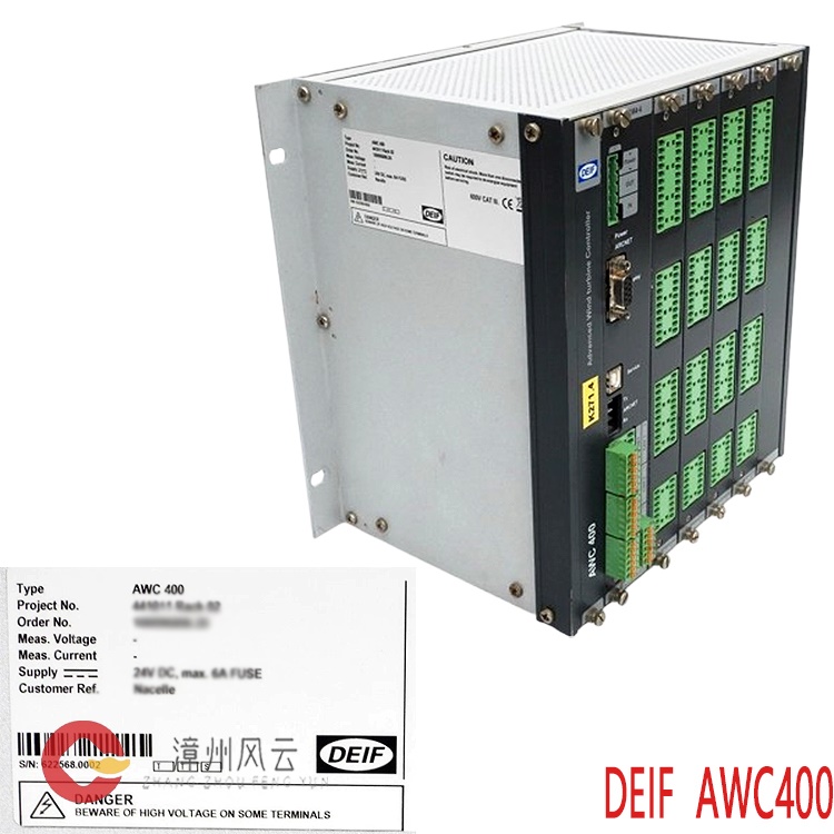
It collects three-phase voltage and three-phase current transformer signals, and uses the TDM (Time Division Multiplication) algorithm to calculate three-phase active power. Unaffected by waveform distortion or three-phase imbalance, it accurately identifies forward active power (overload) and reverse active power (reverse power) DEIF, targeting multiple generators operating in parallel. When a generator's prime mover fails or loses throttle, other generators supply power to it, turning the generator into a motor (reverse power). The system detects the reverse active power, delays the tripping of the generator circuit breaker, and prevents damage to the generator and avoids cascading overload tripping of other generators.
Many products are not yet listed. Please contact us for more product information.
If the product model differs from the displayed image, the model number shall prevail. Please contact us for specific product images; we will arrange to take photos in our warehouse for confirmation.
We have 76 shared warehouses worldwide, so it may sometimes take several hours to accurately return the information to you. We apologize for the inconvenience. Of course, we will respond to your inquiries as soon as possible.
Other names for RMP-112D:
RMP-112D Protective Relay
Overload Protection Relay RMP-112D
RMP-112D Reverse Power Relay
I. Core Functions
Overload Protection: Monitors the generator's active power to prevent the prime mover from being overloaded. When the generator's active power output exceeds the set threshold, a relay trip signal is output after a delay to protect the diesel/gas turbine prime mover and prevent damage from an excessive load.
Overload setting: 25%-125% Pn (rated power)

Adjustable action delay: 0-20s
Reverse power protection: For parallel operation of multiple generators. When the prime mover of one unit fails or the throttle is lost, other units supply power to that unit, turning the generator into a motor (reverse power). The RMP-112D detects the reverse active power and, after a delay, trips the generator circuit breaker to prevent damage to the unit and avoid cascading overload tripping of other units.
Reverse Power Setting: 0-25% Pn
Adjustable Action Delay: 0-20s
II. Status Indicators
POWER: Module Power Indicator
OVERLOAD P>: Overload Warning Indicator; RELAY: Overload Protection Action Output Indicator
REVERSE POWER -P>: Reverse Power Warning Indicator; RELAY: Reverse Power Protection Action Output Indicator
III. Output Circuit
Two independent relay passive contact outputs, corresponding to overload and reverse power respectively, can be connected to circuit breaker tripping and alarm circuits; contact capacity 8A/250VAC, self-locking version optional.
Acquires three-phase voltage and three-phase current transformer signals, uses TDM time-division multiplication algorithm to calculate three-phase active power, unaffected by waveform distortion and three-phase imbalance, accurately identifies forward active power (overload) and reverse active power (reverse power) DEIF.
The system calculates the actual active power from the collected U and I values;
.jpg)
this is then compared to the threshold value set by the knob;
an internal delay timer is activated when the threshold is exceeded;
upon the timer's completion, the corresponding relay contact closes, outputting a trip/alarm signal;
automatic reset occurs when the fault disappears (optional self-locking latch).
Supported wiring modes: 2W3 (2CT three-phase three-wire), 3W3 (4) (3CT three-phase three-wire / four-wire)
IV. Typical application scenarios
Marine power stations: Multiple diesel generators connected in parallel, prime mover overload protection, reverse power disconnection protection (most commonly used) DEIF land-based standby generator sets, distributed power stations, multi-generator parallel systems
Generator sets with insufficient prime mover power margin, focus on preventing overload damage to the diesel engine
V. Common fault diagnosis
Power indicator light not on: Check auxiliary power supply voltage;
False trip: Verify CT/PT wiring polarity. Reverse power is very sensitive to wiring polarity; reverse polarity will continuously report reverse power;
No trip: Check power setting knob, delay time, CT ratio setting, and confirm that the transformer circuit is intact. DEIF RMP-112D Overload & Reverse Power Protection Relay
VI. Working Principle
This relay is an electronic static power protection relay. It adopts the TDM (Time Division Multiplication) measurement principle to acquire the generator's three-phase voltage (PT) and three-phase current (CT) signals, calculate the three-phase active power, and simultaneously identify the power magnitude and direction, realizing two independent protection logics for overload protection and reverse power protection.
1. Signal Acquisition and Power Measurement Principle
Voltage and current are internally isolated and transformed, converting high-voltage, high-current signals into weak electrical signals;
Active power (P=U×I×cosφ) is calculated using the TDM algorithm, unaffected by harmonics and three-phase imbalance, and can distinguish between forward active power (generator supplying power) and reverse active power (grid supplying power to generator – reverse power) DEIF;
The relay internally compares the measured active power with the threshold set by the panel potentiometer.
.jpg)
Supported wiring: 2W3 (2 current transformers), 3W3/4 (3 current transformers), compatible with marine three-phase three-wire and three-phase four-wire substations (DEIF).
2. Overload Protection Principle (Excessive Forward Power)
Normal: The generator outputs positive active power. If the power is less than the set overload value, the protection will not operate.
Fault Condition: Overload, active power > set overload threshold (25-125% Pn).
When the positive power exceeds the set value, the OVERLOAD indicator light on the panel illuminates.
A timed delay timer (adjustable from 0-20s) is activated to avoid instantaneous load impacts and prevent false tripping.
When the delay ends, the overload output relay contacts actuate, outputting a passive switching signal to drive the generator circuit breaker to trip and alarm.
When the actual power falls below the threshold, the fault is automatically reset (latching can be set).
Protection Purpose: To prevent the diesel engine prime mover from being overloaded for a long time and to avoid damage to the prime mover. 3. Reverse Power Protection Principle (Power Direction Reversal)
Only applicable to multiple generators operating in parallel.
Normal: The generator outputs active power in the forward direction, and the protection is locked.
Fault Condition: The diesel engine shuts down, the governor malfunctions, or fuel is cut off, causing the prime mover to lose power; the generator remains connected to the bus and is driven by other parallel units, turning the generator into a motor, with active power flowing in reverse into the generator body.
The relay detects that the active power direction has reversed, and the reverse power exceeds the reverse power setting value (0-25% Pn);
The REVERSE POWER indicator light illuminates, initiating a reverse power delay (0-20s) to avoid the short-term reverse impact during synchronous grid connection;
Upon the delay, the independent reverse power relay contacts close, outputting a trip signal to disconnect the faulty unit from the grid;
This prevents damage to the prime mover caused by being driven in motor mode and also avoids other operating units additionally carrying the load of this motor, causing a system cascading overload trip.
4. Output and Reset Logic
Overload and reverse power outputs are provided by two completely independent passive relays, which do not interfere with each other and can be connected to alarm and trip circuits respectively.
Default: Automatic reset after fault disappearance; configurable latching mode, manual reset required after fault operation.
Contact capacity: 8A/250VAC, directly drives circuit breaker trip coil or alarm circuit.
5. Key Points to Note
CT and PT polarity is crucial; reverse polarity will cause a false reverse power trip during normal operation.
This relay measures active power, not current. It will still trip if the active power exceeds the limit but the current is within the limit.
The delay function is to avoid grid disturbances and instantaneous load fluctuations; instantaneous operation is not used.
Recommended related products:
DEIF ATC-PLANT
DEIF XL192
DEIF PCM4-2
DEIF PCM4-1
DEIF PCM4-3
DEIF PCM4-4
DEIF PCM5-2
DEIF AGI 315
DEIF AGC 245
DEIF AGC 243
DEIF SG-C4
DEIF PPU/2/GS
DEIF DGU 4
DEIF AGI410
DEIF SCM 4-2
DEIF IOM 4-1
DEIF PCM 4-1
DEIF DGU 0004
DEIF AGC200
DEIF XL144
DEIF SGC 242
DEIF SGC 241
ROLLS-ROYCE-H1111.0104
ROLLS-ROYCE-H1111.0102
ROLLS-ROYCE-H1127-0101
ROLLS-ROYCE-H1111.0103
More......
.jpg)
.jpg)
Address
Room 205, Office Building, No.1 Chaoyang North Road, Longwen District, Zhangzhou City, Fujian Province
fengyunfadacai@qq.com
Sales consultant
Miss.Green
+86 15860249102