.jpg)
.jpg)
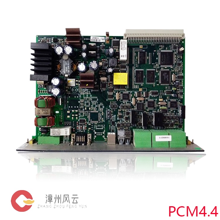
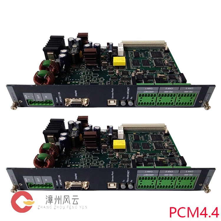
It is the core acquisition board of the DGU generator main control unit, responsible for the acquisition, isolation, transmission, and signal preprocessing of all electrical quantities of the power grid/generator, providing raw electrical data for main control, protection, and load distribution. When multiple units are running in parallel, it synchronously uploads accurate active/reactive values. The DGU relies on this data to achieve accurate load sharing and active/reactive differential control; it detects load distribution deviations, provides early warnings of hidden unit defects such as fuel filter blockage and governor failure, and triggers fault disconnection when necessary.
Many products are not yet listed. Please contact us for more product information.
If the product model differs from the displayed image, the model number shall prevail. Please contact us for specific product images; we will arrange to take photos in our warehouse for confirmation.
We have 76 shared warehouses worldwide, so it may sometimes take several hours to accurately return the information to you. We apologize for any inconvenience. Of course, we will respond to your inquiries as soon as possible.
I.
Basic Positioning
The IOM 4-1 is a three-phase high-precision electrical quantity measurement and transmission PCB module (6TE rack-mount card type) for the DEIF Delomatic DM-4 marine/land-based generator set PMS energy management system. Its full name is Signal Converter Module 4.1, and it is the core acquisition board of the DGU generator main control unit. It is responsible for the acquisition, isolation, and transmission of all electrical quantities from the power grid/generator, as well as signal preprocessing, providing raw electrical data for main control, protection, and load distribution.

Power Supply: 24VDC, installed in the DM4 system rack I/O slot, hardware address DIP switch setting.
II.
Core Hardware Architecture (PCB Circuit Partitioning)
High-Voltage Isolation Sampling Circuit (2.5kV Electrical Isolation)
Three-phase voltage direct input 0~690VAC; three-phase current connected to CT secondary 1A/5A; independent high-voltage divider and current shunt sampling, complete isolation between strong and weak currents, protecting the main control board.
Hardware Filtering Circuit
Each channel has a built-in 6th-order analog hardware filter to filter out generator rectifier harmonics and inverter interference, capable of acquiring harmonic components up to 500Hz.
High-Precision AD Converter Unit (0.5-level accuracy IEC60688)
Multi-channel synchronous high-speed ADC, synchronously acquiring U/I waveforms and calculating instantaneous electrical parameters.
Signal Processing MCU
Onboard independent microcontroller, real-time calculation of power, power factor, imbalance, frequency, etc.; local threshold judgment and over-limit alarm.
Transmitter Output Drive Circuit
Two isolated 4~20mA analog outputs, capable of forwarding measured values to external instruments/PLCs.
System Bus Interface
Backplane parallel bus for high-speed data exchange with the DGU main control CPU; CAN bus expands the HMI DU-2 and AOP operation panels.
Self-Test and Fault Detection Circuit
Self-diagnosis for CT disconnection, PT undervoltage, loose terminals, and abnormal board power supply.
III.
Complete Core Functions
1. Three-Phase Full-Parameter High-Precision Electrical Measurement (Core Function)
Directly acquires generator/bus three-phase voltage and three-phase current, with onboard calculation and output of all electrical quantities:
Basic Quantities: Line voltage/phase voltage, phase current, frequency 40~70Hz;
Power Quantities: Active power (P), reactive power (Q), apparent power (S), power factor (cosφ);
Energy Statistics: Forward/Reverse active and reactive energy;
Abnormal Characteristics: Three-phase voltage imbalance, current imbalance, harmonic content, phase sequence detection;
Accuracy 0.5 class, meeting the metering requirements of ships and power plants, supports PT 100/110V, CT 1A/5A transformation ratio software configuration, no hardware jumper DEIF modification required.
2. Electrical Fault Pre-detection (Relieves Main Control Processing Pressure)
The board locally determines faults in real time and uploads alarm flags:
PT open circuit/phase loss, CT open circuit (prevents CT high-voltage breakdown);
Overvoltage/undervoltage, overfrequency/underfrequency, reverse power, current overload;
Severe three-phase imbalance, incorrect phase sequence;
Fault signals are quickly sent to the DGU via the backplane bus, driving audible and visual alarms and unit trip protection.
3. Isolated Analog Transmitter Output (4~20mA)
Two independently isolated 4~20mA analog outputs, with software-mapped measurement parameters:
Example: One outputs active power, and the other outputs frequency, directly connecting to a third-party PLC, recorder, or field pointer meter to expand system data externally.
4. PMS Power Distribution Underlying Data Support
When multiple units are operating in parallel, the IOM 4-1 synchronously uploads its precise active/reactive power values. The DGU relies on this data to achieve precise load sharing and active/reactive power differential control; it detects load distribution deviations, provides early warnings of hidden unit defects such as fuel filter blockage and governor malfunctions, and triggers fault disconnection when necessary.
5. System Communication and Interaction
High-speed parallel bus on the rack backplane: Uploads raw sampled waveforms, calculated parameters, and fault status to the DGU main controller in real time;
CAN bus expansion interface: Connects to the local operation panel AOP-2 and display unit DU-2 for local viewing of voltage, current, and power;
Board address DIP switches: When multiple IOM 4-1 racks coexist, distinguish between generator bus and shore power measurement circuits.
6. Hardware Self-Diagnosis and Reliability Assurance
2.5kV strong and weak current isolation, meeting the 690V Class III overvoltage safety standard for ships;
Continuously monitors terminal tightness and board 24V power supply status;
CT open circuit protection: Immediately blocks internal operations after the detection current loop is disconnected, preventing secondary high voltage from damaging the equipment;
Wide temperature range: -20℃~+55℃, suitable for harsh environments such as ship engine rooms and industrial power plants.
IV.
Complete Working Principle Flow
Step 1: Primary Electrical Signal Isolation and Sampling
Generator/shore power three-phase voltage is directly connected to the IOM 4-1 voltage terminal (maximum 690VAC); CT secondary 1A/5A current is connected to the current terminal.
The high-voltage divider resistor and precision current shunt inside the PCB complete the strong and weak current conversion. The 2.5kV isolation barrier prevents primary high voltage from entering the control circuit, ensuring the safety of the control system.
Step 2: Hardware Filtering and Noise Reduction
The sampled signal enters a 6th-order low-pass hardware filter to filter out diesel generator harmonics, inverter interference, and switching operation spikes, outputting a smooth standard sine wave to the ADC.
Step 3: Synchronous AD Analog-to-Digital Conversion
Multi-channel synchronous ADCs simultaneously acquire the instantaneous waveforms of three-phase voltage and current, converting the analog AC signal into a digital data stream and uploading it to the onboard MCU.
Step 4: Onboard MCU Real-Time Calculation (Local Signal Processing)
The microcontroller quickly performs Fourier transform and power algorithm calculations based on discrete sampling points:
Basic RMS value, frequency;
Active power, reactive power, power factor;
Three-phase imbalance, harmonics;
Simultaneously, it compares the results with software-preset protection thresholds; if a threshold is exceeded, a fault code is generated.
Step 5: Multi-channel Data Distribution
Backplane bus upload to main controller DGU: All measured values, fault markers, and waveform data are transmitted to the DGU core controller for unit start-up/shutdown, parallel connection, protection, and load distribution logic;
4~20mA transmitter output: The MCU converts engineering parameters to a 4~20mA standard industrial analog signal and outputs it in isolation to external monitoring equipment;
.jpg)
CAN bus download to operation panel: Simplified parameters are sent to DU-2/AOP for local display and operation;
Step 6: Fault Closed-Loop Protection Linkage
When the IOM 4-1 detects serious faults such as CT open circuit, reverse power, or overvoltage, it immediately sends an emergency fault frame to the DGU; upon receiving the signal, the DGU executes: audible and visual alarm, load reduction, circuit breaker tripping, and shutdown protection to prevent generator and bus equipment burnout.
V.
Typical Application Scenarios
Maritime Power Plant DM4 PMS System: Each generator is equipped with one IOM 4-1 data acquisition unit for power output and one for shore power, enabling parallel operation, load sharing, and reverse power protection;
Land-based distributed diesel/gas power plants and combined heat and power (CHP) unit monitoring;
Off-grid microgrid energy management system, responsible for multi-source electrical quantity acquisition and protection front-end.
VI.
Supplementary Key Electrical Specifications
Voltage Measurement: 0~690Vrms direct measurement, supports PT step-down 100/110V;
Current Measurement: CT secondary 1A/5A, continuous 10A withstand, short-term 300A 1s overload;
Isolation Withstand Voltage: 2500VAC (measurement and control circuits);
Frequency Range: 40~70Hz (suitable for marine 50/60Hz dual frequency);
Transmitter Output: 2-channel isolated 4~20mA, load ≤500Ω;
Power Supply: 24VDC, power consumption approximately 8W;
Protection: Pollution degree 2, overvoltage category III, compliant with EN61010 safety standards.
Recommended
related products:
DGU-3
DEIF
IMD 122C
DEIF
IMD 122B
DEIF
IOM 220
DEIF
AGC 222
DEIF
AGC 246
DEIF
BRW-2
200-0-200 DEIF
IMD 122A
DEIF
IMD 100
DEIF
DGU 4
DEIF
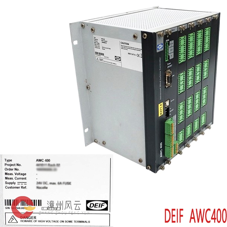
AWC 400
DEIF
DEIF DGU
0003
More......
.jpg)
Address
Room 205, Office Building, No.1 Chaoyang North Road, Longwen District, Zhangzhou City, Fujian Province
fengyunfadacai@qq.com
Sales consultant
Miss.Green
+86 15860249102