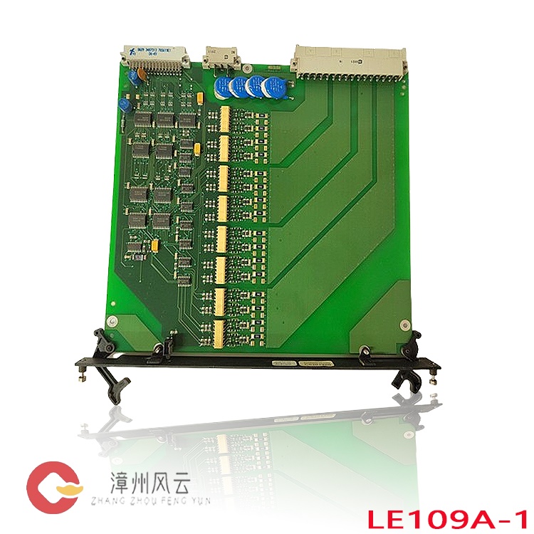
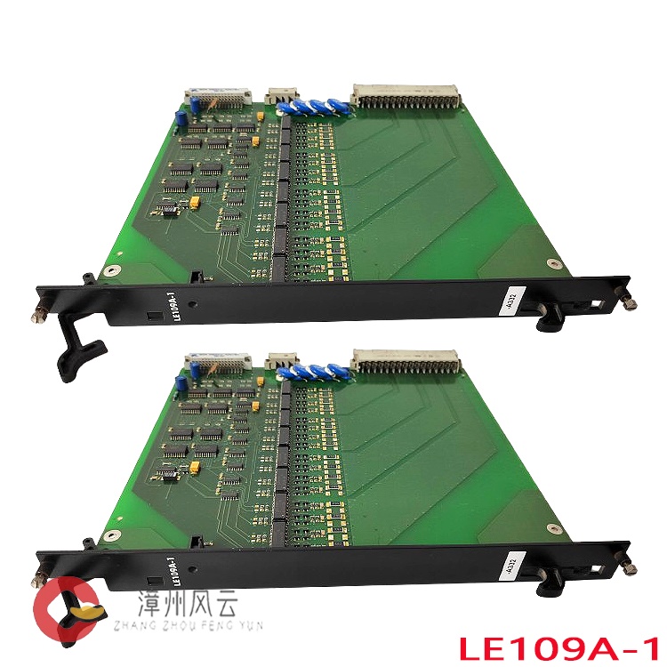
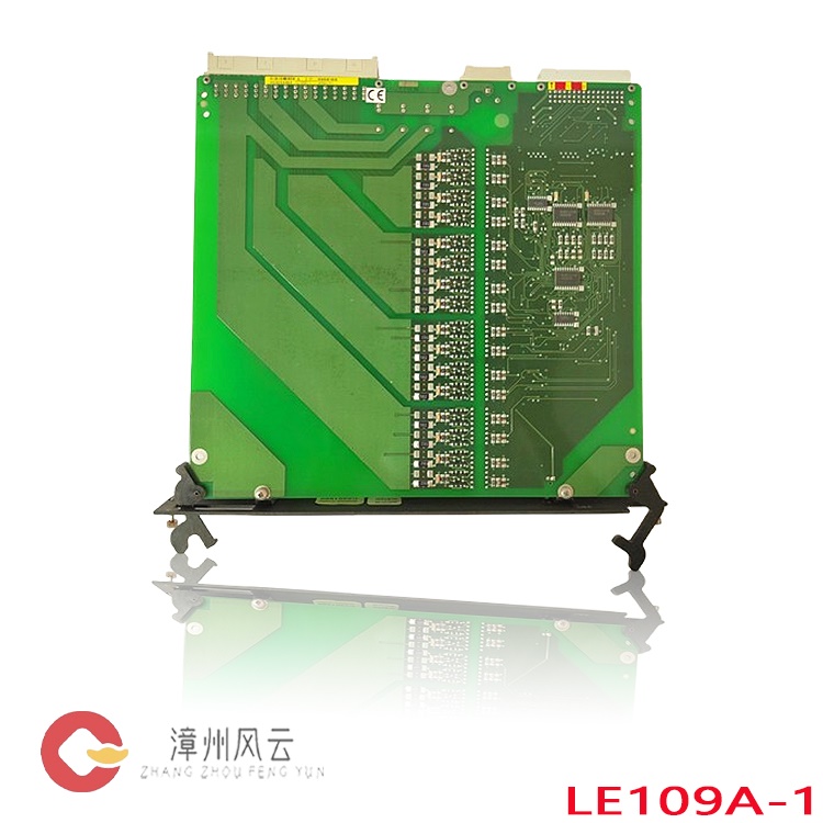
Utilizing a multi-layer PCB architecture with integrated circuit isolation, the module employs onboard signal acquisition channels to perform real-time sampling, filtering, and isolated conversion of the cabinet’s 24V DC power supply circuits and field feedback signals. A dedicated internal logic processing unit continuously monitors supply voltage and circuit status—detecting faults such as undervoltage, overvoltage, power loss, or abnormal signals—while transmitting processed, standardized data to the main control unit via a high-speed backplane bus. Simultaneously, it receives commands from the higher-level control system to output discrete control signals, enabling functions such as power circuit interlocking, fault reporting, and safety-related interlocks. The module features dual redundant logic channels and automatically enters a "fail-safe" mode in the event of a malfunction; this prevents a single-point failure from destabilizing the entire control system, ensures the integrity of signal links amidst power fluctuations or electromagnetic interference, and guarantees the reliable execution of logic on the power supply side of the automated control system.
All products listed on this website are specialized items; their market prices are subject to frequent fluctuations.
Please rely on the quotes provided by our customer service team. As some items may be new additions, the prices displayed may not be final or accurate.
Before placing an order, please confirm the specific model, product details, and pricing with our customer service representatives. We offer both used and new equipment; please contact us to discuss your requirements.
I. Operating Principle
The NRD108028 utilizes a multi-layer PCB isolation circuit architecture. Leveraging onboard signal acquisition channels, it performs real-time sampling, filtering, and isolated conversion of the 24V DC power supply circuits within the cabinet, as well as field feedback signals. The module features a dedicated internal logic processing unit that continuously monitors supply voltage and circuit status—detecting faults such as undervoltage, overvoltage, power loss, or abnormal signals. Processed, standardized signals are transmitted to the main control unit via a high-speed backplane bus. Simultaneously, the module receives commands from the higher-level control system and outputs switching control signals, enabling functions such as power circuit interlocking, fault reporting, and safety interlock operations. Equipped with dual redundant logic channels, the module automatically enters a "fail-safe" mode in the event of a malfunction. This prevents a single-point failure from destabilizing the entire control system, ensures the integrity of signal links amidst power fluctuations or electromagnetic interference, and guarantees the reliable execution of logic on the power supply side of the automated control system.
II. Product Advantages
High-Reliability Industrial-Grade Hardware Design: Built with wide-temperature-range components and vibration-resistant PCB construction, the module supports continuous operation from -10°C to +60°C. It features EMC (electromagnetic compatibility) protection and is resistant to vibration and dust. Designed for harsh control cabinet environments—such as those found in power plants or heavy industrial facilities—it offers a low failure rate during long-term, continuous operation.
Robust Signal Isolation and Interference Immunity: Electrical isolation between power circuits and signal circuits effectively suppresses field harmonics and surge interference. This eliminates false signals caused by crosstalk, ensuring that power monitoring data remains accurate and stable. Redundant Safety Architecture: Features dual-channel independent logic paths and supports safety-redundant configurations. Designed to meet safety instrumentation requirements in the energy sector, it ensures a "fail-safe" state and reduces the risk of operational downtime.

Native Compatibility with ALSTOM Control Platforms: Supports original ALSTOM bus protocols and can be installed directly into standard rack slots. It integrates seamlessly with ALSTOM-series DCS and turbine control systems, while remaining compatible with mainstream PLC and DCS platforms—facilitating easy system retrofitting and spare-part replacement.
Compact Rack-Mount Design: Utilizes a standard DIN-rail or rack-mount card structure, minimizing cabinet space requirements. The clear layout of terminal blocks simplifies centralized wiring, routine inspections, and maintenance, while ensuring rapid replacement of components.
Real-Time Fault Diagnostics: Equipped with built-in loop self-testing mechanisms that detect power supply anomalies, channel disconnections, and bus communication errors in real time. Fault locations are reported immediately, shortening troubleshooting time and minimizing losses from unplanned downtime.
III. Applicable Industries and Functions
Thermal/Gas Power Generation: Deployed within DCS control cabinets for steam turbines and boilers. It monitors DC power supply paths, executes power-failure interlocks and power-loss protection logic, and ensures the continuity of the main control system—serving as a critical component in power plant safety control loops.
Oil, Gas, and Chemical Processing: Installed in central control cabinets to monitor power supply circuits for explosion-proof field control units. It triggers interlock protection during anomalies, preventing process instability caused by power fluctuations.
Rail Transit Control Systems: Used for power monitoring in onboard or trackside signaling control cabinets. It assists in diagnosing the status of signaling systems and provides power-supply safety interlocking, ensuring the stable operation of signaling equipment. Automation for Heavy Industry and Large-Scale Equipment: In automated control cabinets for large-scale wind turbines, hydro-turbine units, and complete metallurgical equipment, these modules serve as power signal conditioning and interlocking boards. They coordinate the power supply status of various sub-units, enabling staged system power-up and fault isolation.

Water Treatment and Municipal Energy Automation Projects: Within the DCS (Distributed Control System) of large-scale pumping stations and energy facilities, these modules centrally collect the status of multiple power sources and report them to a unified monitoring platform, facilitating remote, visual management of power supply status.
Core Function Summary: Acting as the "monitoring and safety hub" on the power side of an entire automation system, these modules perform five key functions: power status acquisition, signal isolation and conditioning, fault detection, safety interlocking output, and bus data exchange. They prevent the propagation of power anomalies, protect expensive primary control equipment, and ensure continuous production and operational safety.
IV. Standard Operating Procedures
Operators must be certified electrical automation engineers familiar with Alstom DCS rack specifications.
Pre-installation Inspection: Verify the model (NRD108028) and inspect the module for any signs of burning or terminal deformation. Wear an anti-static grounding wrist strap to discharge static electricity. Ensure the rack is completely powered down and that no residual voltage remains on the backplane.
Rack Installation and Securing: Align the module with the rack slot guide rails and slide it in steadily. Ensure the backplane bus connector is fully engaged, then tighten the top and bottom mounting screws to prevent loosening due to vibration. Complete external terminal wiring according to the schematics, ensuring clear distinction between power input channels, signal channels, and grounding terminals; verify that all connections are secure.
Pre-power-up Review: Double-check the wiring sequence and the reliability of the ground connection. Confirm that the supply voltage is 24V DC, and verify that there are no short circuits or incorrect wiring. Clean the interior of the cabinet to remove any dust or foreign objects. Power-on Commissioning: Gradually apply control power to the cabinet and observe the status indicators on the circuit boards. Use the configuration software on the host computer to identify the modules, set channel parameters, define alarm thresholds (upper and lower limits), and configure interlock logic. Systematically test the system by simulating undervoltage and wire-break conditions to verify that fault reporting and interlock outputs function according to the design logic.
Operational Monitoring: Once the system is in operation, use the host monitoring interface to check module power supply readings, channel status, and communication status. Maintain regular operational logs.
Removal and Replacement: Disconnect the main power supply for the rack and allow sufficient time for the capacitors to discharge completely. Disconnect the terminal wiring, loosen the mounting screws, and carefully slide out the module. After installing a replacement module, reconnect the wiring, verify the parameters, and then restore power.
This model does not support hot-swapping; removing or inserting the module while the power is on is strictly prohibited.
V. Precautions
Electrostatic Discharge (ESD) Protection: The circuit boards contain sensitive CMOS chips. Always wear a grounded anti-static wrist strap when handling, transporting, or servicing the equipment. Spare modules must be stored in their original anti-static shielding bags in a dry, well-ventilated environment, away from corrosive gases. Do not touch the chips or solder joints on the circuit boards with bare hands.
Power Supply Requirements: The rated supply voltage is 24V DC. Never connect the device to high-voltage AC power. It is recommended to install voltage regulation and surge protection devices on the power supply line to prevent transient high-voltage spikes from damaging the circuit board components.
No Live Operations: Always disconnect the power and verify that the equipment is de-energized before performing any installation, wiring, or module removal/insertion tasks. Inserting or removing modules while the power is on can destroy the backplane bus, damage module firmware, and cause total system failure.
Environmental Control: Ensure the operating environment is free from condensation, corrosive gases, and excessive dust. Keep the cabinet well-ventilated—do not obstruct cooling vents—and ensure the temperature remains within the specified operating range. Wiring and Grounding: Ensure signal grounds and power grounds are separated and grounded according to specifications, with grounding resistance meeting industrial control standards. Apply appropriate torque to wiring terminals; excessive tightening can damage PCB pads, while insufficient tightening may lead to poor contact or intermittent faults.

Spare Parts and Version Compatibility: Prioritize using spare parts with the same version. If using a different version, verify firmware compatibility beforehand to prevent bus communication errors.
Fault Handling Principles: When a module triggers an alarm, first determine whether the issue stems from an external power supply fault or damage to the module itself; avoid repeatedly cycling the power to test the unit. Do not attempt to disassemble or repair faulty boards, as this may cause further damage; instead, have them inspected by a professional industrial control service provider.
Compliance Requirements: Adhere to electrical safety standards and project-specific SIL (Safety Integrity Level) safety requirements during operation and maintenance. Any modifications to interlock logic must undergo a formal approval process, and the system must be thoroughly tested following such changes before being put back into service.
Recommended products:
P141121A2A0150C
P70035W82V
PIB101C
PIB1201A
PIB310
PIB903
1241000031D AGI 307
1044220080D OPM-1
SCM-B 1044220110F
SCM-A 1044220100F
More......
Address
Room 205, Office Building, No.1 Chaoyang North Road, Longwen District, Zhangzhou City, Fujian Province
fengyunfadacai@qq.com
Sales consultant
Miss.Green
+86 15860249102