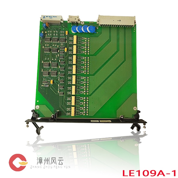
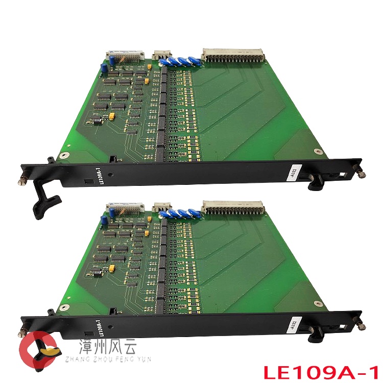
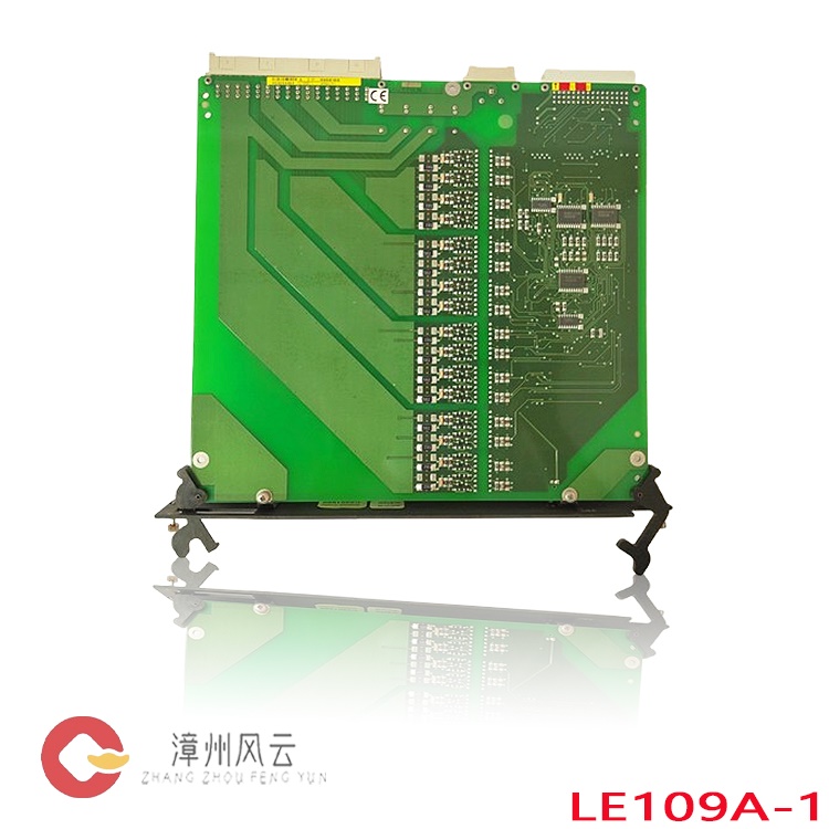
This module serves as a core field control board within the Alstom ALSPA control system architecture. Designed for use with the CE2000 field controller, it incorporates built-in control algorithms to perform PID calculations, logic interlocking, and threshold-based evaluations according to preset parameters. It issues control commands to field actuators and executes protective logic, triggering alarms or initiating shutdown sequences should process parameters exceed safe thresholds. The module communicates with the higher-level F8000 system via a WorldFIP bus (at a data rate of 1 Mbps) and interfaces with local human-machine units through an RS485 port. This facilitates bidirectional data exchange, enabling the transmission of real-time field data and alarm events to the upper-level system, while simultaneously receiving parameters and control commands from it.
All products on this website are specialized items; their market prices are subject to constant fluctuation.
Please rely on the quotes provided by our customer service team. As some items are new, the prices listed may not be final.
Before placing an order, please confirm the specific model, product details, and pricing with our customer service representatives. We offer both used and new units; please contact us to discuss your requirements.
Alternative
names for the AM164:
Processing Unit Board AM164
AM164 Digital/Analog Module
Communication Module AM164
I.
Product Overview
The ALSTOM AM164 is a core field control board within the ALSTOM ALSPA control system architecture. Designed for use with the CE2000 field controller, it utilizes the WorldFIP industrial bus to facilitate data exchange between field devices and the higher-level F8000 control system. As a module specialized for signal acquisition and logic processing in power plants and industrial process control, it is widely employed in power generation units, petrochemical facilities, and large-scale industrial automation systems. It handles field signal acquisition, computational control, fault diagnosis, and communication relay functions, serving as a primary hardware unit for the retrofitting and spare-part replacement of legacy ALSTOM control systems.
II.
Operating Principle
The AM164 control board features a high-performance microprocessor and is organized into four main functional modules: signal acquisition, logic computation, fault diagnosis, and bus communication.
Signal Acquisition: This module receives analog signals (such as temperature, pressure, or flow) and digital/switching signals from field sensors. It performs signal filtering, analog-to-digital conversion, and signal isolation, effectively eliminating signal distortion caused by electromagnetic interference in the field environment. Logic Operations: Features built-in control algorithms that perform PID calculations, logic interlocking, and threshold monitoring based on preset parameters. It outputs control commands to field actuators and executes protective logic—triggering alarms or system shutdowns if process parameters exceed safe thresholds.
Bus Communication: Interacts with the higher-level F8000 system via a WorldFIP bus (at a 1 Mbps data rate) and communicates with local human-machine interface (HMI) units through an RS485 interface. This enables bidirectional data exchange, allowing for the transmission of real-time field data and alarm events to the upper-level system, while receiving parameters and control commands in return.

Fault Self-Diagnostics: Equipped with an onboard, real-time hardware diagnostic mechanism that continuously monitors power supply, communication links, and I/O channel status. Upon detecting channel anomalies, communication interruptions, or hardware failures, the system automatically logs fault codes and issues alarm notifications. Fault records are stored in non-volatile memory—ensuring they are retained even during power outages—which facilitates effective root-cause analysis.
III.
Core Product Advantages
Robust Adaptation to Harsh Industrial Environments: The board utilizes ruggedized, industrial-grade components and is designed for a wide operating temperature range. It offers high resistance to vibration and electromagnetic interference (EMI), making it well-suited for power plant environments characterized by high temperatures, dust, humidity, and strong electromagnetic fields. Designed for rack-mounting within control cabinets, it ensures high stability and a long service life.
High Integration and Scalability: A single board can manage multiple I/O modules, supporting the expansion of up to 16 I/O units. It handles the acquisition of both analog and digital signals, reducing the amount of hardware required inside control cabinets, saving installation space, and simplifying the wiring design of the entire control system.
Stable Communication Architecture with Redundancy Support: Native support for the WorldFIP industrial bus ensures high transmission rates and excellent real-time data performance. The system supports dual-communication-link redundancy; in the event of a primary link failure, it automatically switches to a backup channel. This prevents a single point of failure from causing a loss of communication across the entire control system, thereby enhancing the operational reliability of the unit. Built-in self-diagnostics facilitate convenient operation and maintenance. The hardware performs real-time self-checks and provides clear fault codes. It logs operational activities and alarm events, enabling rapid identification of faulty channels and the nature of issues. This simplifies on-site troubleshooting, shortens downtime for maintenance, and reduces overall operation and maintenance costs.
The system offers excellent compatibility and supports easy spare-part replacement. As a standard component within the ALSPA series, it integrates directly with CE2000 field controllers. In retrofit projects for legacy Alstom control systems, it allows for the replacement of spare parts without requiring extensive modifications to the existing control logic, significantly reducing the scope of the upgrade work.
IV.
Applications in Various Industries
1. Power Generation (Thermal, Hydro, Gas Turbine, and Waste-Heat Power Plants)
This is the primary application area for the AM164. It is used for data acquisition and interlock control—monitoring parameters such as bearing temperatures, lubricating oil conditions, cylinder wall temperatures, and flue gas metrics for steam, hydro, and gas turbines. It enables real-time monitoring of process parameters and provides over-temperature/limit protection, ensuring the safe and stable operation of power generation units. In retrofit projects for aging power plants, it serves as a critical spare part, extending the operational life of existing control systems and avoiding the high costs associated with replacing an entire Distributed Control System (DCS).
2. Petrochemical Industry
Used for data acquisition and interlock protection in large-scale compressors, reactors, and pumping stations. By monitoring pressure, temperature, and flow signals, it facilitates closed-loop process control. In the event of equipment anomalies, it triggers protective actions rapidly, preventing process-related accidents and ensuring continuous chemical production.

3. Large-Scale Industrial Automation
Applied in sectors such as metallurgical heat treatment, large-scale HVAC-controlled cleanrooms, and industrial extrusion production lines. It provides high-precision monitoring of process variables and PID closed-loop control, stabilizing production parameters, enhancing product consistency, and reducing energy consumption. Summary of Overall Industry Value
As a core control component at the field level, the AM164 establishes a data link between field sensors/actuators and higher-level control systems. It enables a combination of local field control and remote monitoring, thereby enhancing the safety redundancy of the entire automation system and reducing the risk of unplanned downtime. In the maintenance and operation market for existing imported equipment, the AM164 serves as a direct replacement for original components, effectively addressing challenges such as the discontinuation of legacy hardware and shortages of spare parts, ultimately extending the service life of the complete equipment system.
V.
Operating Procedures
Note: All hardware operations must be performed by certified industrial control professionals. Verify all wiring before powering on the device.
Installation and Hardware Wiring: With the power disconnected, insert the AM164 module into the designated rack slot and secure the locking mechanism. Complete the wiring for power supply, analog signals, digital signals, and the WorldFIP bus according to the technical drawings. Ensure proper separation between signal cables and power cables, implement a single-point ground connection, and conduct continuity and insulation tests on the wiring.
Pre-Power-On Checks: Confirm that the supply voltage matches the module's specifications, ensure there are no short circuits or incorrect wiring, and verify a reliable ground connection. Check that other modules within the rack are functioning correctly, and remove any debris or dust from around the module.
Power-On and Initialization: Apply power and observe the status indicators on the module; wait for the self-test process to complete. Once the self-test is successful, the module will enter a standby communication state. Establish a communication link via the supervisory control system (host computer) or a local operator terminal.
Parameter Configuration: Use the supervisory control system software to configure I/O channel types, measurement ranges, alarm thresholds, PID parameters, and interlock logic. Download these parameters to the memory of the AM164 module and save them.
Commissioning and Testing: Simulate field signal inputs to verify data acquisition accuracy. Test interlock, alarm, and protection logic to ensure that output responses function as expected. Verify the transmission of data over the bus, including the uploading of process data and the downloading of control commands. Normal Operation: During standard operation, the board automatically collects, processes, and uploads data, requiring no frequent local intervention. Operations and maintenance personnel can monitor real-time data, review alarm logs, and verify the board's operational status via a host computer (workstation).
Shutdown and Replacement: For maintenance-related shutdowns, first disable the associated interlock protections, disconnect power to the rack, release the retaining clips, and remove the board. After installing a replacement, follow the procedures for wiring, powering on, downloading parameters, and performing logic testing.
VI.
Precautions
Safety Protocols: All wiring, insertion, or removal of boards must be performed only after the power has been completely disconnected. "Hot-swapping" the AM164 control board is strictly prohibited; doing so could cause electrostatic discharge (ESD) damage to chips, burn out the board, or lead to equipment damage or unintended activation of protection systems. Personnel must implement anti-static measures, including the use of an anti-static wrist strap.
Wiring and Grounding: Use shielded cables for analog signals, with the shield grounded at a single point. Route signal cables separately from high-power electrical cables, maintaining a safe distance to prevent high-voltage interference from causing signal drift. The board’s grounding terminal must be securely connected to a protective ground; the grounding resistance must meet specified standards, and the terminal must never be left unconnected (floating).
Environmental Requirements: Ensure the control cabinet is well-ventilated for heat dissipation; keep the board’s ventilation openings free from dust and oil accumulation. Do not install the board in environments prone to condensation, high corrosivity, or the presence of flammable/explosive substances. Maintain the operating temperature within the product's rated range; exceeding this range will accelerate component aging and shorten the board's service life.

Parameter Management: Always back up existing parameters before making any changes. Any modifications to interlock or protection parameters must follow a formal work-permit procedure, including proper safety isolation, to prevent accidental changes that could trigger unintended unit protection actions. After downloading parameters, confirm that they have been saved; verify that the settings are retained even after a power cycle. Routine Maintenance: Regularly inspect the status of the board/card indicator lights and clean dust from the cabinet. Perform calibration of analog channels every 12–24 months. In the event of a fault alarm, first check the board/card error codes and inspect the wiring and sensors before determining whether the board/card itself is damaged. Do not disassemble the electronic components on the board/card.
Spare Parts and Storage: Store spare AM164 boards/cards in anti-static packaging within a dry, temperature-controlled environment. Avoid subjecting them to severe vibration or impact during handling and storage. When replacing parts, prioritize the use of original or verified, qualified components to prevent compatibility issues.
Fault Handling: If a communication interruption or channel error occurs, immediately assess the process risks. If necessary, temporarily disable the associated interlocks before proceeding with troubleshooting. Strictly prohibit any unauthorized modification of the board/card’s underlying control logic while the unit is in a critical phase of operation.
Recommended
products:
AGI
115-2 1241000013A
PIB101
-CAN ALSTOM
DIZ232-CAN
ALSTOM
ICP232-CAN
ALSTOM
SPU232.2-5-CAN
ALSTOM
SPU232.1-CAN
ALSTOM
SPU232.2
029.366.817
DEIF
PCM5.2
DEIF
AWC500
DEIF
TMS2-4
DPD 99158
1044500040C
GC-1F/2
100105108.30
SIM-Q LF
2961740050 05
700014780.20
CP-1
DEIF DPD
99150
1241000031D
AGI 307
1044220080D
OPM-1
SCM-B
1044220110F
SCM-A
1044220100F
More......
Address
Room 205, Office Building, No.1 Chaoyang North Road, Longwen District, Zhangzhou City, Fujian Province
fengyunfadacai@qq.com
Sales consultant
Miss.Green
+86 15860249102