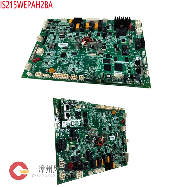
The GE 151X1207CK02SA12 is a 77 mm thyristor-based de-excitation module designed by General Electric (GE) for use with EX2100 / EX2100e excitation control systems (specific compatibility depends on the unit configuration and accompanying technical documentation). It is installed within the de-excitation branch of an excitation power cabinet or auxiliary cabinet. Together with the IS200EDEX de-excitation control board, a de-excitation resistor (or inductor), and a 41 DC contactor (or de-excitation switch), it forms a rapid de-excitation circuit. Its function—though singular—is absolutely critical: it provides a controlled discharge path for the immense energy stored in the generator rotor magnetic field during normal unit shutdowns, fault-triggered trips, or emergency shutdowns.
Many products have not yet been listed online; please contact us for information on our full range.
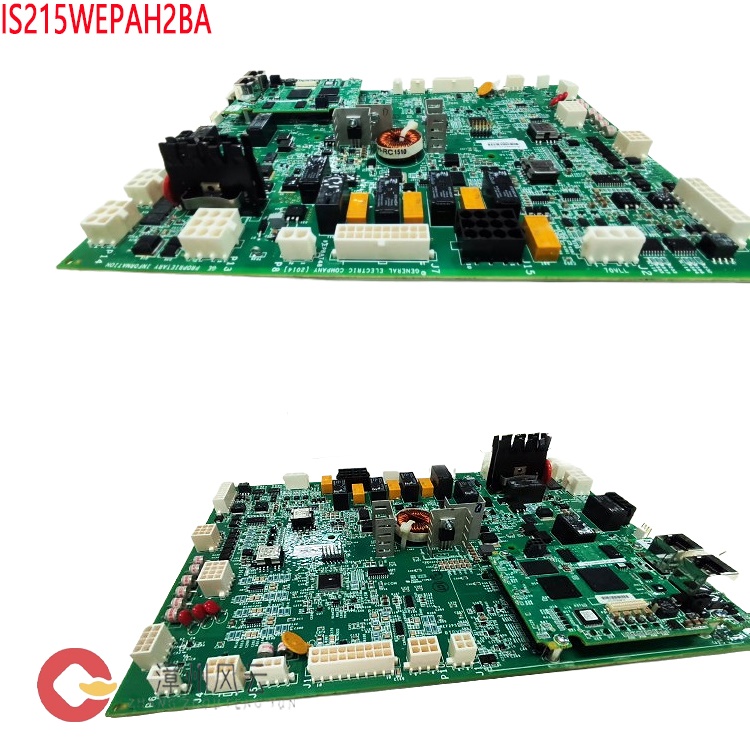
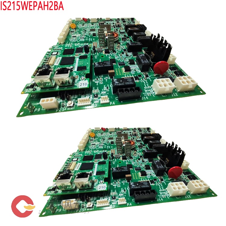
If there is a discrepancy between a product model number and the displayed image, the model number takes precedence. Please contact us if you would like to see specific product photos; we can arrange for our warehouse team to take pictures for verification.
We operate 76 shared warehouses globally, so it may occasionally take a few hours to provide you with an accurate response. We appreciate your patience and will address your inquiries as quickly as possible.
I. Product Identification and Model Classification
(A) Model and Series Classification
The part number 151X1207 belongs to a family of components for the GE EX2100 excitation system, which includes various parts such as control units, power components, and field discharge (de-excitation) components. The "CK02" designation refers to the specific configuration and component combination of the field discharge module, while "SA12" serves as a revision or version suffix. It is important to note that differences in GE part number suffixes often indicate variations in component ratings, busbar configurations, snubber/absorption circuits, or the versions of associated circuit boards. Therefore, components with the same base part number but different suffixes are not necessarily interchangeable based on appearance alone. Before proceeding with a replacement, please verify the module’s nameplate, the accompanying technical documentation, and the configuration list for your unit’s excitation system.

(B) Understanding the "77 mm" Specification
The "77 mm" designation refers to the chip diameter of the module’s primary
switching device—the press-pack thyristor (SCR). Within the EX2100 series, power
bridges and field discharge branches are categorized by device size, with
standard specifications including 100 mm, 77 mm, 53 mm, and 42 mm. The bridge
capacity and field discharge capability decrease as the device size decreases.
The 77 mm variant falls into the medium-to-high power category and is suitable
for units with larger rotor time constants and higher field discharge energy
requirements.
(III) Component Ratings and Configuration
According to publicly available third-party spare parts documentation, thyristors within the CK02 family are generally rated at approximately 4400 V / 1850 A. For the specific voltage and current ratings of the 151X1207CK02SA12 model, one should refer to the module’s nameplate or the technical documentation provided by GE; it is not advisable to simply apply parameters from other variants within the same family. The standard configuration of the module includes press-pack thyristors, a heatsink with clamping hardware, an RC snubber network, a Hall-effect current sensor, and an IS200EDEX field-discharge control board mounted on the module. The EDEX board handles gate triggering and conduction feedback, and it maintains operational capability even during brief losses of control power.
(IV) Role within the System
In a static excitation system, routine voltage regulation is performed by the three-phase fully controlled bridge within the Power Conversion Module (PCM). The field-discharge module does not participate in regulation; rather, it serves as an execution component within the protection and shutdown chain. This functional role dictates its design philosophy: the priority is not regulation precision, but rather absolute reliability—ensuring that the unit functions exactly when required.
II. Operating Principle
(I) The Necessity of Field Discharge
A generator rotor acts as a large inductor, typically characterized by a time constant of several seconds. If the field breaker is opened during a unit trip—abruptly interrupting the rotor current—the resulting rate of change in current induces dangerous overvoltages across the rotor windings, the excitation transformer, and the power bridge. This can cause insulation breakdown or damage to the thyristors. The correct approach is to provide a low-resistance path for the rotor current simultaneously with the opening of the field circuit. This allows the magnetic field energy to be transferred to a field-discharge resistor, where it is dissipated as heat, enabling the field current to decay rapidly and controllably to zero. (II) Two Paths: Normal Shutdown and Emergency Tripping
During a normal shutdown, the control system first drives the power bridge to its inversion (retard) limit, reversing the bridge output and allowing the field current to decay naturally. Once the current drops to an acceptable level, the field contactor is opened; in this scenario, the field-discharge module typically does not handle the bulk of the energy. In the event of an emergency trip, the protection system immediately opens the 41A/41B DC contactors. Since the field energy must find an immediate path for dissipation, the field-discharge module is triggered into conduction, absorbing the entire discharge current. The differences between these two operating conditions dictate that the triggering circuit must be fast, precise, and independent of any external power supply.

(III) The Triggering and Conduction Process
Upon receipt of a trip command, the EXHS board opens the field contactor. The state of its auxiliary contacts, combined with the status of the bridge AC power switch and the operational state of the bridge, establishes the conditions for triggering. These inputs are fed into two independent triggering circuits located on the EDEX board. Each circuit outputs gate pulses to trigger the field-discharge thyristors. At this stage, the field polarity has already reversed, making the thyristor anode positive relative to the cathode—a condition that enables conduction. Current then flows through the field-discharge resistor, allowing the energy to dissipate. If the field polarity has not yet reversed, the thyristors will not conduct, even if gate pulses are present; this inherent physical characteristic serves as a safeguard against accidental or erroneous activation.
(IV) Triple-Trigger Protection
The first layer is a dual-channel independent trigger system: the two trigger circuits utilize separate control power supplies and Hall-effect current sensors. Either channel can initiate a trigger, preventing a single point of failure. The second layer is an overvoltage self-trigger mechanism: if the voltage between the anode and the gate exceeds the breakdown threshold of the series-connected breakdown diodes, the device triggers automatically, without requiring any external command. The third layer is a power-loss holdover feature: the EDEX board incorporates a voltage-retention circuit, ensuring that a trigger can still be executed even during a brief loss of control power. Combined, these three layers ensure that the field-suppression capability remains intact, even in extreme scenarios—such as the simultaneous loss of control power and a failure of the trigger board itself.
(V) Conduction Feedback and Parallel Expansion
The Hall-effect sensors on the EDEX board are positioned within the air gap of a toroidal iron core to detect the discharge current flowing through the thyristor. These two independent sensing channels serve both to confirm successful field suppression and to report the system status back to the control system; if no conduction feedback is received, the event is treated as a field-suppression failure. For high-capacity units, multiple field-suppression modules can be connected in parallel. In this configuration, one EDEX board is designated as the "master" and the others as "slaves"; the master receives the trigger signal and relays it to the slaves, ensuring synchronized triggering.
(VI) Distinction from a "Crowbar" Circuit
A "crowbar" circuit is designed to suppress high negative voltages induced
in power conversion modules during a "pole slip" (loss of synchronism) event. It
operates via a self-triggering mechanism and is typically found in salient-pole
generators, such as those used in hydroelectric power plants. While field
suppression and a crowbar circuit share similar functions, they serve different
purposes: the former manages energy dissipation during shutdown, while the
latter addresses overvoltage surges during operation. In some EX2100 systems,
both functions are integrated into a single module, sharing a common discharge
resistor. When selecting equipment, it is essential to distinguish between a
"field-suppression module" and a "combined field-suppression and crowbar
module," as they are not interchangeable.
(VII) Exceptions in 42 mm Topology
In configurations utilizing a 42 mm non-inverting bridge, the bridge arms incorporate built-in freewheeling diodes. During a trip event, these diodes provide a discharge path, eliminating the need for a separate field-discharge module. The use of DC contactors is strictly prohibited in such systems, as the freewheeling diodes must remain connected to the rotor circuit at all times. Understanding this is crucial to avoid the incorrect addition or removal of field-discharge components during retrofit projects.
III. Structure and Key Design Aspects
(I) Press-Pack Thyristor Assemblies
The 77 mm thyristors feature a double-sided press-pack design, relying on external clamping force to establish electrical and thermal connections, with no internal solder layers. Compared to stud-mount or modular-type devices, these offer superior current-carrying capacity, surge-current tolerance, and thermal cycling longevity—characteristics well-suited for field-discharge applications, which are typically characterized by long periods of inactivity followed by the handling of high-amplitude, long-duration tail currents. Their primary failure mode is a short circuit, which is easily detected through circuit monitoring or by the operation of a fuse.
(II) Heat Dissipation and Clamping
The devices are clamped between aluminum or copper heatsinks, with the required pressure applied via insulated tie rods, disc springs, and clamping bolts. Insufficient pressure leads to increased contact thermal resistance and localized overheating, while excessive pressure can crack the silicon chip. During installation, it is mandatory to use specified torque values and proper clamping tools, applying pressure evenly in a diagonal sequence.
(III) RC Snubber Networks
An RC snubber circuit connected in parallel across the thyristor suppresses
commutation overvoltages and the rate of voltage rise ($dv/dt$), preventing the
device from triggering unintentionally. Over time, the capacitors and resistors
within these snubber circuits may age; should they fail, the device’s
overvoltage protection capability is compromised. Consequently, these components
are a primary focus during maintenance and inspection.
(IV) Control and
Detection
The EDEX board integrates trigger circuitry, Hall-effect sensors, status indicators, and test interfaces. Its dual power supply inputs and dual sensing/test terminals serve as primary access points for on-site static testing and fault localization.
(V) Insulation and Busbars
The module is secured within the cabinet using insulating supports. Busbars are selected based on the RMS value and short-duration peak value of the field-suppression current; contact surfaces must be kept clean and coated with conductive grease. In corrosive environments—such as coastal areas or chemical plants—the condition of protective coatings and seals must also be inspected.
IV. Technical Advantages
(I) Rapid Field Suppression for Rotor Insulation Protection
Upon triggering, the thyristor immediately establishes a low-impedance path, ensuring the discharge process is completed within the designed timeframe. A faster decay of the field current minimizes the duration for which the rotor windings, excitation transformer, and power bridge are subjected to overvoltage, thereby reducing the risks of insulation aging and inter-turn damage.
(II) Fail-Safe Design Philosophy
The system incorporates four independent mechanisms: dual-channel triggering, overvoltage-triggered self-activation, power-loss state retention, and conduction feedback. These components operate autonomously; no single-point failure can lead to a total loss of the field-suppression function. This aligns with the fundamental requirement for generator sets: "protection functions must not be lost due to any single failure."
(III) Component Margins Suited for Harsh Operating Conditions
The 77 mm press-pack devices offer high current-carrying and surge-handling
capabilities, enabling them to withstand the initial current impulse during a
trip event as well as the subsequent, long-duration energy dissipation.
Furthermore, double-sided cooling ensures a more gradual rise in junction
temperature, which helps extend the service life of the components.
(IV)
Modularity and Scalability
Standardized modular architecture minimizes the variety of spare parts required and reduces replacement time. Furthermore, units of varying capacities can be accommodated through a master-slave parallel configuration, eliminating the need to develop separate field-discharge (de-excitation) systems for each capacity rating.
(V) Observability of Operational Status
Conduction feedback and event logging transform the field-discharge process from a "black-box" operation into a verifiable one. Following every trip, it is possible to confirm whether the field-discharge function was successfully executed. This provides a reliable basis for condition-based maintenance, ensuring that issues are identified proactively rather than being discovered only during a subsequent failure.
(VI) Mature Ecosystem for Spare Parts and Maintenance
The EX2100 series boasts a large installed base, supported by a well-established infrastructure for module testing, repair, refurbishment, and replacement. For power plants in long-term operation, this translates to significantly shorter downtime.
V. Impact on Relevant Industries
(I) Heavy-Duty Gas Turbines and Combined-Cycle Power Plants
GE gas turbine generators are typically equipped with EX2100/EX2100e excitation systems. Rapid field discharge ensures safe disconnection of the unit during protection-triggered events, load rejection, or emergency shutdowns. This mitigates the risk of rotor damage caused by overvoltage and reduces the time required for pre-restart inspections.
(II) Steam Turbines and Conventional Thermal Power Plants
Large-capacity units feature long rotor time constants and high stored energy; the current-carrying margin of the field-discharge module is a critical factor in ensuring a smooth tripping process. The 77 mm module variant is commonly employed in medium-to-large capacity units, serving as the execution component for the "final line of electrical protection."
(III) Hydropower Generation
Salient-pole generators carry a higher risk of losing synchronism (pulling
out of step). In these applications, the field-discharge module is frequently
paired with a "crowbar" circuit. This combination not only facilitates field
discharge during a trip but also suppresses overvoltage resulting from a loss of
synchronism, thereby protecting both the rotor and the power bridge.
(IV)
Nuclear Power Plant
Conventional Islands, Captive Power Plants, and Waste Heat
Power Generation
In these scenarios, where high availability is required and maintenance windows are short, the module’s dual-channel triggering and status feedback capabilities are particularly valuable—helping to mitigate the risk of inadvertent operation while reducing the need for unnecessary downtime for inspections.
(V) Grid Security and System Stability
Rapid field suppression shortens the recovery time of terminal voltage following a fault, thereby reducing the impact on adjacent generating units. This is especially critical for weak power grids, isolated grid operations, and black-start scenarios.
(VI) Spare Parts Supply and O&M Services
A modular design allows for maintenance, repair, and operations (MRO) to be managed at the module level rather than requiring entire cabinets as spare parts, which reduces capital tied up in inventory. Furthermore, refurbishment and testing services extend the technical lifespan of existing, in-service units.
VI. Operational Procedures
(I) Pre-installation Inspection
Verify the nameplate drawing number, component rating, and accompanying technical documentation. Inspect the thyristor ceramic housings for cracks, check the heat sinks for deformation, and examine busbar contact surfaces for signs of oxidation or arcing. Measure the insulation resistance of the main circuit, ensure that the RC snubber circuit components are intact, and confirm that the EDEX board version, DIP switch settings, and jumpers align with the specific unit configuration.
(II) Mechanical Installation
Secure the components by tightening fasteners in a diagonal sequence to the torque values specified in the technical manual; use a torque wrench and mark each bolt after tightening. Ensure that cooling air ducts remain unobstructed and that the cooling fans rotate in the correct direction. Clean the busbar contact surfaces, apply conductive grease, and tighten the connections to the specified torque. (III) Verification of Electrical Wiring
Check the polarity of both trigger circuits, the P24V control power supply, and ensure that the two power supply paths originate from independent sources and are protected by separate fuses. Also, verify the orientation of the Hall-effect sensors, as well as the cabinet grounding and shielding connections.
(IV) Pre-commissioning Tests
Perform static trigger tests with the main circuit de-energized to verify the gate pulses for both channels. Measure the DC resistance and insulation of the main circuit, check the cooling fan interlocks, and simulate a trip sequence to confirm the integrity of the entire chain: "Contactor 41 opening — auxiliary contact actuation — EDEX triggering — conduction feedback." Test records must be archived to serve as a baseline for future condition monitoring.
(V) Normal Operation
The module does not participate in active regulation; routine operation requires only the monitoring of EDEX status indicators, conduction feedback, internal cabinet temperature, and cooling fan operation. If an abnormal condition is detected—even if it has not yet triggered a trip—an inspection should be scheduled for the next available shutdown window; the system should not be left to operate for an extended period while a fault is suspected.
(VI) Procedures Following Shutdown or Tripping
Field de-excitation during shutdown is handled automatically by the EXHS; it is strictly prohibited to introduce manual delays, bypass the function, or install additional intermediate relays. After de-excitation, confirm that the field current has decayed to zero before proceeding with any switching operations. Following any trip, retrieve the event logs and inspect the thyristors, fuses, de-excitation resistors, and busbar temperature rise; perform conduction tests if necessary.
(VII) Inspection of Parallel-Connected Modules
In systems with multiple modules connected in parallel, verify that the master and slave configurations are correct, that trigger signals are being relayed properly, and that current is distributed relatively evenly across all modules. If an individual module is replaced, a synchronized trigger test must be performed again. (VIII) Spare Parts Replacement
Replacements must utilize components with the same part number or those confirmed by GE to be interchangeable. Additionally, the EDEX version and the parameters of the absorption circuit must be verified. When mixing components from different batches, the impact of variations in turn-on characteristics on current sharing must be evaluated.
VII. Precautions
(I) Personnel and Equipment Safety
The rotor circuit carries high voltage and high energy; field-discharge resistors remain at high temperatures for an extended period after operation. During maintenance, strict adherence to the following procedures is mandatory: de-energization, voltage verification, discharging, grounding, and the application of "Lockout/Tagout" (LOTO) protocols. Do not approach the resistors until they have cooled down. It is strictly prohibited to insert or remove circuit boards or touch busbars while the excitation system is energized.
(II) Do Not Rely on "Feel" for Clamping Pressure
The clamping force applied to pressure-contact components directly determines their service life and operational safety. Specified tools, torque values, and disc spring assemblies must be used. During repeated disassembly and reassembly, disc springs or shims must be replaced in accordance with the manufacturer’s manual; simply "tightening" components using a standard wrench is prohibited.
(III) No Switches or Time Delays in the Field-Discharge Circuit
The field-discharge branch must remain intact and capable of immediate conduction. Introducing switches, time-delay relays, or modifying trigger logic will extend the discharge duration during a trip, potentially compromising the rotor insulation.
(IV) Do Not Arbitrarily Alter Discharge Resistance
The parameters of field-discharge resistors or inductors are specifically engineered for the unit. Increasing the resistance value may accelerate current decay but will also lead to higher overvoltages; conversely, decreasing the resistance value will prolong the field-discharge time. Any replacement must be based on formal calculations and confirmed by the manufacturer.
(V) Redundancy Must Not Be "Consolidated"
Dual trigger power supplies, dual sets of fuses, and dual sensors must remain entirely independent of one another. In the field, two separate circuits are sometimes connected to the same terminal for the sake of "neat wiring." This effectively eliminates redundancy—a modification that is both subtle and hazardous.
(VI) Environment and Storage
Control cabinets must be kept ventilated, dust-free, and moisture-proof. In coastal or chemical-industrial environments, special attention should be paid to the potential for salt-spray or sulfide-induced corrosion on busbars and terminals. Spare parts must be stored in a moisture-proof environment; crimped components should not be stacked or subjected to pressure. For long-term storage, the insulation and physical condition of the components should be inspected periodically.
(VII) Maintenance Scope
Pressure-contact thyristor assemblies are factory-assembled units; field conditions are generally unsuitable for disassembly or re-crimping. If a component is damaged, the entire unit should be replaced or returned to the manufacturer for repair. Disassembling the heatsink on-site is strictly prohibited.
(VIII) Documentation and Traceability
Records—including installation torque, insulation resistance, trigger test results, trip events, and replacement history—must be archived. Field-discharge (de-excitation) is a one-time protective action; without proper documentation, it is impossible to verify whether the system will function correctly the next time it is required.
VIII. Frequently Asked Questions
Q1: Are 151X1207CK02SA12 and CK02SA02 directly interchangeable?
A: Both belong to the 151X1207 CK02 series and share essentially the same mounting interface. However, differences in the suffix may indicate variations in component rating, busbar configuration, or the version of associated circuit boards. Before swapping, you must verify the nameplate specifications, EDEX version, and the excitation configuration file for the specific unit—do not rely solely on physical appearance.
Q2: Can a 53 mm module be used as a replacement for a 77 mm module?
A: This is not recommended. The dimensions of a component are directly related to its current-carrying capacity and surge-withstand capability. Using a smaller, lower-rated component provides no safety margin for extreme operating conditions—such as those encountered during field discharge—and could lead to component failure or the failure of the field-discharge function. Q3: What are the common reasons why a thyristor fails to conduct after a trip?
A: Possible causes include: the magnetic field polarity has not yet reversed; the trigger circuit lacks a P24V power supply; the EXHS auxiliary contact signal has not reached the EDEX unit; the gate circuit is open; or the component itself is damaged. Troubleshooting should be conducted in the following order: signal, power supply, and then the component.
Q4: Is it normal for the field-discharge resistor to become hot after activation?
A: Yes, it is normal. The energy from the magnetic field is dissipated as heat through the resistor. However, if the temperature rise is significantly higher than historical records, or if there are signs such as unusual odors or discoloration, you should check for resistance drift, loose connections, and ventilation conditions.
Q5: Is there a fixed replacement interval for the field-discharge module?
A: No. Replacement should be based on condition-based maintenance. Decisions should be made by evaluating factors such as trigger test results, on-state voltage drop, insulation levels, the number of trips, and years of service. During major overhauls, particular attention should be paid to the snubber (absorption) circuit and the contact pressure of the clamped components.
Q6: Is a "crowbar" circuit mandatory?
A: It is not a standard, universal component. Whether it is required depends on the type of generator (e.g., the risk of out-of-step operation in salient-pole machines), system study conclusions, and manufacturer recommendations. When required, it is typically integrated into the field-discharge module, sharing the same discharge resistor.
IX. Conclusion
In an excitation system, the field-discharge module often goes unnoticed—it is only remembered during the few hundred milliseconds of a trip event. Precisely for this reason, its true value lies not in its technical specifications, but in its reliability. Features such as dual independent triggering, self-triggering upon overvoltage, fail-safe operation (maintaining state during power loss), and conduction feedback are all designed to ensure that when the module *must* act, it *definitely* acts. For operating entities, verifying drawing numbers and component ratings during selection, strictly adhering to specified clamping forces and torque values during installation, and maintaining test records during maintenance are far more effective than any remedial measures taken after the fact.
Recommended products:
151X1215GD01SA21
151X1225DB02MP01
151X1202YE04PP01
151X1225DB01SA04
151X1207BC52SA01
151X1225EK01PC03R
151X1230BS01WH05
151X1230BR02SA02
151X1207BB50SA01
151X1228FG01PC02B
151X1207BB55SA01
151X1233DD01SA01R3
151X1220BR01NP01
151X1220FG01PC01
151X122EK01PC04
151X1233DD01SA01R
151X1230HA01MG01C
151X1207BB53SA01
More......
Address
Room 205, Office Building, No.1 Chaoyang North Road, Longwen District, Zhangzhou City, Fujian Province
fengyunfadacai@qq.com
Sales consultant
Miss.Green
+86 15860249102