.jpg)
.jpg)
This is a three-phase RMS (Real Effective Value) voltage integrated protection relay that collects the three-phase line voltages (L1/L2/L3) and calculates the effective values in real time. It is specifically designed for monitoring the voltage of generator sets, ship power distribution, plant transformers, and motor busbars using DEIF (Digital Effective Value Interchange). It is also compatible with land/marine classification certifications (DNV/ABS/LR).
Many products are not yet listed. Please contact us for more product information.
If the product model differs from the displayed image, the model number shall prevail. Please contact us for specific product images; we will arrange to take photos in our warehouse for confirmation.
We have 76 shared warehouses worldwide, so it may sometimes take several hours to accurately return the information to you. We apologize for any inconvenience. Of course, we will respond to your inquiries as soon as possible.
I. Basic Positioning and Measurement Principles
TheDGU4 is a three-phase RMS true RMS voltage integrated protection relay, corresponding to ANSI protection codes: 27 (undervoltage protection) + 59 (overvoltage protection). It is specifically designed for DEIF monitoring of generator sets, marine power distribution, plant transformers, and motor bus voltage. It is also compatible with land/marine classification certifications (DNV/ABS/LR).
Collects three-phase line voltages (L1/L2/L3) and calculates the effective value in real time;
Undervoltage logic: Compares the lowest three-phase voltage to a threshold value;
Overvoltage logic: Compares the highest three-phase voltage to a threshold value;
Auxiliary power supply wide-range adaptive: 85~265V AC/DC universal, no additional transformer required.
II. Core Protection Functions (Adjustable Thresholds)
1. Undervoltage Protection U<(ANSI 27)
Adjustment range: 80%~100% of the rated voltage Un;
Action logic:If the voltage of any phase remains below the set threshold, the undervoltage relay contacts flip after a delay;
Protection function: Disconnects the switch in case of generator loss of excitation, grid voltage drop, phase loss, or sudden low-voltage load, preventing motor stall and burnout, excitation equipment damage, and circulating current in parallel units.
.jpg)
Application scenarios: Protects the motor, rectifier, and excitation system from burnout due to low voltage in cases of grid voltage loss, generator excitation fault, sudden voltage drop due to load increase, and islanded low voltage. 2. Overvoltage Protection U>(ANSI 59)
Adjustment Range: 100%~120% of rated voltage Un;
Operating Logic: If the voltage of any phase remains above the set threshold, the overvoltage relay contacts flip after a delay;
Protection Function: Prevents damage to windings, instruments, frequency converters, and other low-voltage equipment in case of AVR runaway, no-load shedding, grid connection surge, or excessive excitation voltage.
Application Scenarios: Prevents generator overload, AVR voltage regulation failure, grid connection surge overvoltage, and damage to winding insulation and electronic equipment.
3. Independent Adjustable Delay Trip Function (Core Anti-False Trip)
Undervoltage and overvoltage are each equipped with an independent 0~10s potentiometer delay:
In the instant of voltage exceeding the limit, only the yellow alarm light illuminates, and the contacts do not operate;
After the fault duration reaches the set delay, the relay contacts flip, and the red action LED illuminates;
Instantaneous disturbances (closing impulses, short-term voltage drops) automatically reset the timer to prevent false tripping;
Instantaneous response <100ms: timing starts immediately when the voltage exceeds the limit, and resets when the voltage returns to normal;
Prevents false tripping due to instantaneous fluctuations and closing impulses, distinguishing between instantaneous disturbances and persistent faults.
Fastest response detection speed <100ms, extremely fast fault identification DEIF.
4. Voltage Hysteresis (Hysteresis) to Prevent Frequent Jitter
Panel HYS potentiometer adjustment: 1%~10%Un resets the hysteresis.
After undervoltage activation, the voltage rises to "activation threshold + hysteresis" before resetting.
After overvoltage activation, the voltage drops to "activation threshold - hysteresis" before resetting.
This resolves the issue of frequent relay engagement and disengagement caused by voltage fluctuations at critical points.
III. Status Indicator LED Functions
The panel features 4 indicator lights for intuitive differentiation between working/alarm/action status:
POWER (Green): Solid = Relay auxiliary power supply normal; Off = Power failure;
U < Yellow: Undervoltage over-limit warning only (contacts do not move before delay);
U > Yellow: Overvoltage over-limit warning only (contacts do not move before delay);
RELAY Red (two independent channels): Illuminates when undervoltage/overvoltage delay is reached and contacts actuate, corresponding to the fault lockout indicator DEIF.
IV. Output Contact Logic
Two independent relay outputs: 1 undervoltage contact + 1 overvoltage contact, mutually independent;
Each output has 1 set of normally open + normally closed changeover contacts (SPDT);
Contact capacity: 250VAC/24VDC, 8A resistive load;
Optional self-locking version: retains contact state after fault activation, requires power-off reset; standard version automatically resets after voltage recovery.
V. Additional Built-in Fault Detection (integrated into three-phase measurement)
Three-phase acquisition hardware inherently includes monitoring, no additional settings required:
Phase loss protection: any phase disconnection/fuse blown, voltage drops directly, triggering undervoltage protection;
Phase voltage imbalance: single-phase load imbalance, winding short circuit, lowest phase voltage below threshold, undervoltage activation;
Phase sequence error: reversed phase sequence wiring will cause abnormal three-phase voltage deviation, indirectly triggering voltage over-limit alarm.
Multi-channel LED Status Indicators
POWER (Green): Relay power supply is normal;
U < Red RELAY: Undervoltage fault triggered;
U > Red RELAY: Overvoltage fault triggered;
The corresponding indicator light remains on during a fault, allowing for intuitive identification of the fault type.
Dual Independent Isolated Output Contacts
1 set of dedicated undervoltage relays and 1 set of dedicated overvoltage relays, operating independently;
Each set of contacts is equipped with 1 normally open + 1 normally closed (NO/NC) contact, with a capacity of 250VAC/8A;
They can be connected to circuit breaker tripping circuits, audible and visual alarms, and PLC signal circuits, allowing for separate control of tripping and alarms.
200ms Power-Off Lockout Delay: During a brief auxiliary power outage (≤200ms), the contacts remain in their original state, preventing malfunctions and adapting to short-term power grid interruption scenarios.

VI. System Supporting Functions
Electrical Isolation: 3250V withstand voltage isolation between the measurement circuit and output contacts, providing strong anti-interference capabilities.
Certifications: CE, DNV GL, ABS, BV classification society certifications, specifically for marine/offshore platforms.
Measurement Voltage Coverage: 100~690V three-phase line voltage, suitable for low-voltage generator sets and plant power systems.
VII. Power Supply and Adaptation General Functions
Wide-Range Universal Operating Power Supply
Auxiliary Power Supply: 85~265V AC/DC adaptive, AC/DC compatible, suitable for marine 24V DC, industrial 220V AC, and 400V power distribution systems.
Wide Voltage Measurement Range
Measures three-phase line voltage: 57.7~690V AC, supporting mainstream generator/distribution levels of 230V/400V/440V/690V; frequency compatible 40~70Hz (50/60Hz universal) DEIF.
Installation and Interference Resistance: Standard 35mm DIN rail mounting or base mounting; 3250V electrical isolation for input and output, resistant to electromagnetic interference, suitable for harsh environments such as engine rooms and power distribution rooms.
VIII. Typical System Application Logic
Single Generator Operation: Monitors AVR voltage regulation, with delayed tripping for low/high voltage operation;
Multi-unit Grid Connection: Prevents bus overvoltage caused by excitation failure of a single unit;
Ship Main Switchboard: Voltage anomaly protection during shore power/engine power switching;
Back-end Inverter, UPS Front-end: Pre-voltage protection to prevent damage to valuable power electronic equipment.
Industrial self-provided power station/UPS backend: Protects transformers, high-power motors, and frequency converter loads;
Low-voltage distribution cabinet incoming line protection: Promptly disconnects power when the grid voltage is abnormal, preventing damage to downstream equipment.
IX. Differentiation from DGU4/RMV-132D
DGU4: 1 undervoltage + 1 overvoltage combination;
RMV-122D: Dual overvoltage, no undervoltage;
RMV-132D: Dual undervoltage, no overvoltage.
Recommended related products:
DEIF DU-2/MKIII
DEIF DLQ144-PC-NB
DGU-2 DEIF
DEIF DGU2
DEIF PSM-1
DEIF CM-2
DEIF IFM5.1
DEIF IPM-1
DEIF GPM5.1
DEIF PCM4.2
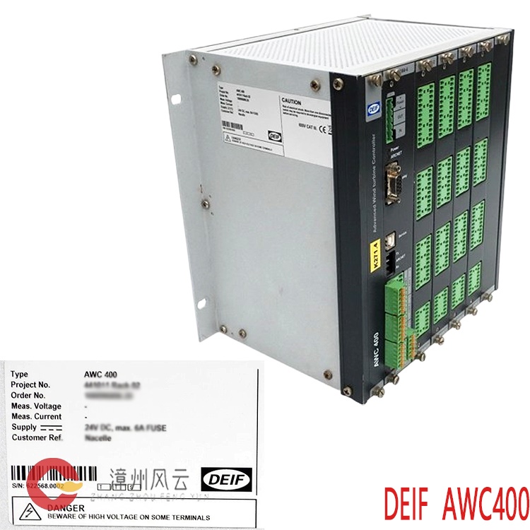
DEIF AWC 400
ROLLS-ROYCE-5880-PC1002
ROLLS-ROYCE-H1111.0204
ROLLS-ROYCE-H1111.0203
ROLLS-ROYCE-H1111.0104
ROLLS-ROYCE-H1111.0102
ROLLS-ROYCE-H1127-0101
ROLLS-ROYCE-H1111.0103
More......
.jpg)
.jpg)
Address
Room 205, Office Building, No.1 Chaoyang North Road, Longwen District, Zhangzhou City, Fujian Province
fengyunfadacai@qq.com
Sales consultant
Miss.Green
+86 15860249102